Optical element holding system, barrel, exposure apparatus, and device manufacturing method

a technology of holding system and lens, applied in the direction of mounting, photomechanical treatment, instruments, etc., can solve the problems of deformation of the surface shape of the lens supported along its entire circumference or at three points on the circumferen

Inactive Publication Date: 2006-04-20
CANON KK
View PDF4 Cites 25 Cited by
  • Summary
  • Abstract
  • Description
  • Claims
  • Application Information

AI Technical Summary

Benefits of technology

[0009] It is accordingly an object of the present invention to provide a unique and improved optical element holding technique by which the shape of an optical element can be adjusted.

Problems solved by technology

In these methods, however, the surface shape of the lens which is supported along its entire circumference or at three points on the circumference would be left deformed due to the weight of the lens itself.

Method used


Image

  • Optical element holding system, barrel, exposure apparatus, and device manufacturing method
  • Optical element holding system, barrel, exposure apparatus, and device manufacturing method
  • Optical element holding system, barrel, exposure apparatus, and device manufacturing method

Examples


first embodiment

[0026] In the present invention, an optical element holding system of the present invention is applied to a projection optical system for use in an exposure apparatus. However, it may be applied also to an illumination optical system of an exposure apparatus or to any other optical systems.

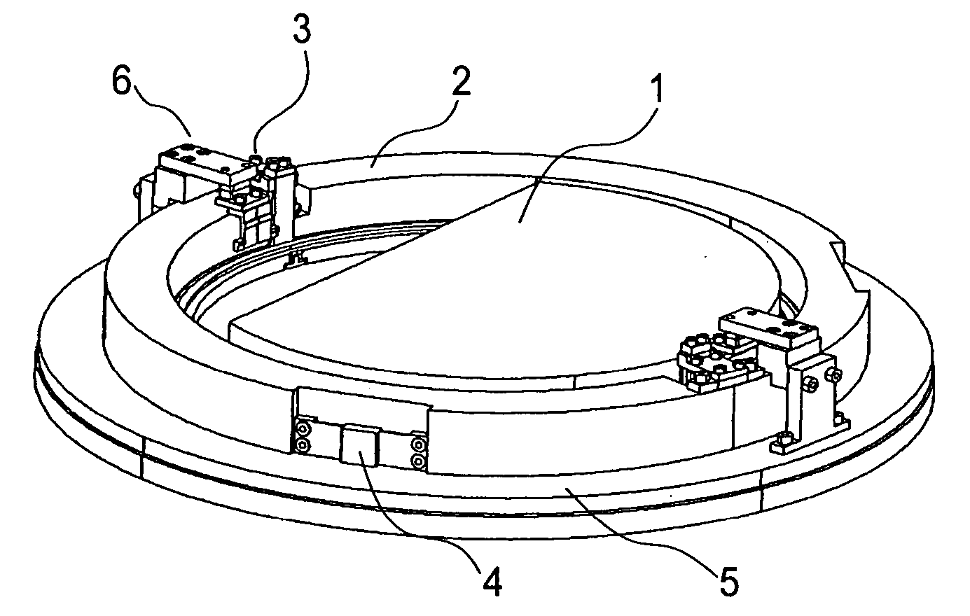
[0027]FIG. 1 is a perspective view of a general structure of an optical element holding system according to the first embodiment of the present invention.

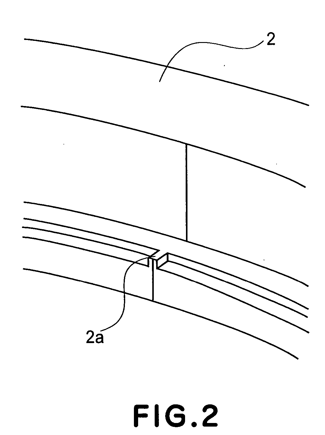
[0028] The optical element denoted at 1 may have any optical function such as reflection, refraction, diffraction, etc. Typically, it may be a mirror, a lens or a diffraction grating. An inner holding member denoted at 2 is held inside an outer holding member 5, and it is arranged to fixedly hold the optical element 1 by use a pair of or more pieces 2a. The inner holding member 2 is provided with a pair of or more driving units 3 arranged to apply at least one of load and displacement to the optical element 1 such as a lens, for example, to ther...

second embodiment

[0060] Next, an optical element holding system according to the present invention will be described.

[0061] With reference to the driving unit 3 of the first embodiment, in place of the bellows 3a, the actuator may comprise a piezoelectric device (3d) having high rigidity and good response.

[0062]FIG. 8 illustrates a driving unit for the optical element holding system according to the second embodiment of the present invention. As regards the position of the piezoelectric device 3d, it may be disposed below the lever member 3b, like the case of the welded bellows 3a of the first embodiment. Since however the piezoelectric device 3d has a short stroke, there is a possibility that the product force thereof is absorbed by the strain of the lever member 3b. In consideration of this, preferably the piezoelectric device should be disposed below the lever member 3c. This arrangement assures direct transmission of the displacement of the piezoelectric device 3d to the optical element 1, with...


PUM


Abstract

Disclosed in this specification are an optical element holding system, a barrel usable therewith, and an exposure apparatus and an exposure method usable therewith. In one preferred form, the optical element holding system includes a ring-like inner holding member which is disposed at an outer periphery of the optical element, for supporting the optical element by use of at least a pair of pieces. The optical element holding system further includes a ring-like outer holding member which is disposed at an outer periphery of the inner holding member and is connected to the inner holding member at plural points. The inner holding member has at least a pair of driving units with an actuator, for supporting the optical element through the actuators.

Description

FIELD OF THE INVENTION AND RELATED ART [0001] This invention relates to an optical element holding system for holding an optical element such as a lens or a mirror, for example. In another aspect, the invention concerns a barrel or an exposure apparatus having such optical element holding system, and a device manufacturing method using such exposure apparatus. [0002] In recent years, reduction projection type semiconductor exposure apparatuses have used a short wavelength light source based on an excimer laser, so as to meet further miniaturization in size of a chip pattern and enlargement in density of a semiconductor chip. The semiconductor exposure apparatus is an apparatus for transferring an original (reticle) having a circuit pattern to a substrate (silicon wafer), and it uses a reduction projection lens by which the circuit pattern can be transferred by exposure onto the substrate. [0003] The projection lens must have an extraordinarily high resolving power to make it possibl...

Claims


Application Information

Patent Timeline
Patent Type & Authority Applications(United States)
IPC IPC(8): G02B7/02
CPCG02B7/026G02B7/028G02B7/181G03F7/70266G03F7/70825G03F7/7085
Inventor MURASATO, NAOKI
Owner CANON KK
Why Eureka
Try Eureka