Filters for communication systems

a filter and communication system technology, applied in the field of filtering for communication systems, can solve the problems of large number of filter coefficients, low over-sampling rate, and large power and silicon area of filter implementations

Active Publication Date: 2006-04-20
MEDIATEK INC
View PDF42 Cites 59 Cited by
  • Summary
  • Abstract
  • Description
  • Claims
  • Application Information

AI Technical Summary

Benefits of technology

[0014] According to a third aspect of the invention, a filter having an input at a first data rate is provided. The filter comprises a decimation filter which receives the input at the first data rate and decreases the data rate from the first data rate to a second data rate that is lower than the first data rate; and a digital filter connected in series with the decimation filter, wherein the digital filter operates at the second data rate.
[0015] According to a fourth aspect of the invention, a method is provided for filtering an input signal at a first data rate. The method comprises decimation filtering the input signal in a decimation filter, wherein the decimation filter decreases the data rate from the first data rate to a second data rate that is lower than the first data rate; and digital filtering the output of the decimation filter in a digital filter at the second data rate.

Problems solved by technology

However, such filter implementations require a large number of filter coefficients, since the number of coefficients required is proportional to the sampling rate, and are complex as well.
Consequently, such filter implementations consume a relatively large amount of power and silicon area.
However, such a low over-sampling rate would put very stringent requirements on the analog anti-aliasing (channel selection) filter in the receiver path and the image rejection filter in the transmitter path.

Method used


Image

  • Filters for communication systems
  • Filters for communication systems
  • Filters for communication systems

Examples


first embodiment

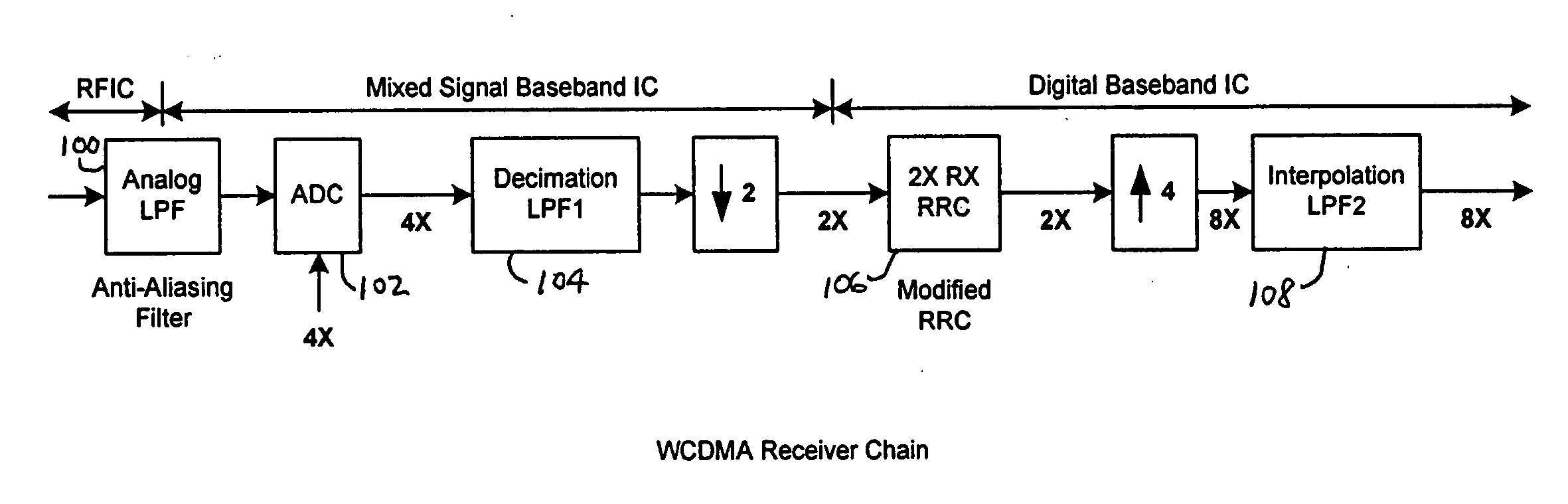
[0026] A block diagram of a WCDMA (wideband code division multiple access) receiver chain including a filter in accordance with the invention is shown in FIG. 3. The receiver chain includes an analog low pass filter 100, an analog-to-digital converter (ADC) 102, a decimation filter 104, a modified RRC digital filter 106 and an interpolation filter 108. The “modified” RRC filter refers to an RRC filter in which the coefficients have been modified to compensate for other components of the entire filter chain as described below. The analog low pass filter 100 is an anti-aliasing filter. The components of the receiver chain are cascaded, or connected in series, to provide and output data rate of 8×. The ADC 102 samples the analog signal at a 4× sampling rate in order to relax the requirement for the analog anti-aliasing filter. Decimation filter 104 may be a low pass filter (LPF) that produces a 2× reduction in data rate. The modified RRC digital filter 106 may be a finite impulse respo...

second embodiment

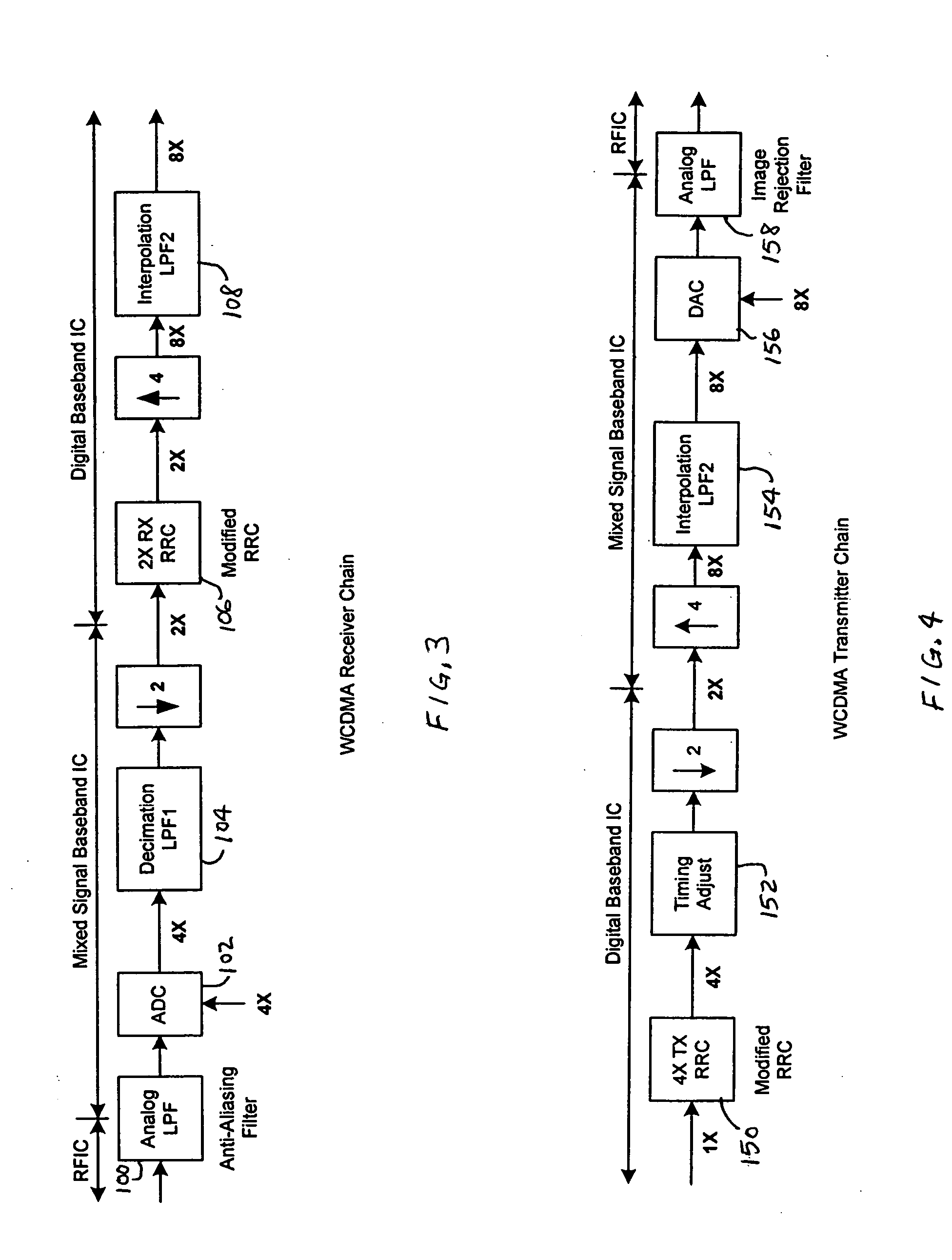
[0030] A block diagram of a WCDMA transmitter chain including a filter in accordance with the invention is shown in FIG. 4. The transmitter chain, which receives a digital signal at a 1× data rate, includes a 4× modified RRC digital filter 150, a timing adjust block 152, an interpolation filter 154, a digital-to-analog converter (DAC) 156 and an analog low pass filter 158. The output of the modified RRC digital filter 150 is supplied to timing adjust block 152 at a 4× data rate. After the timing adjustment, the data rate is reduced to a 2× rate so that the communication between digital baseband and analog baseband ICs is at the lowest rate (i.e. 2× rate) possible. Interpolation filter 154 increases the data rate from 2× to 8×. The DAC 156 has a sampling rate of 8× and provides an analog signal to analog low pass filter 158, which functions as an image rejection filter. The high sampling rate of 8× with DAC 156 relaxes the requirement for the image rejection analog low pass filter. T...

third embodiment

[0033] A block diagram of a TDSCDMA (time division synchronous code division multiple access) receiver chain including a filter in accordance with the invention is shown in FIG. 5. The receiver chain includes an analog low pass filter 200, an ADC 202, a decimation filter 204 and a 2× modified RRC digital filter 206. Unlike the WCDMA receiver, no following interpolation filter is required since rest of the TDSCDMA receiver only requires a 2× data stream. The analog low pass filter 200 functions as an anti-aliasing filter. The ADC 202 has a sampling rate of 4× in order to relax the requirement for the analog anti-aliasing filter. The decimation filter 204 receives the output of ADC 202 at a 4× data rate and reduces the data rate to 2×, thereby supplying samples to the modified RRC digital filter 206 at a 2× data rate. The ADC 202 and the decimation filter 204 are implemented in a mixed signal baseband integrated circuit. The modified RRC digital filter 206 is implemented in a digital ...


PUM


Abstract

The invention relates to a cascaded scheme in which an RRC filter, a modified RRC filter or other digital filter is implemented at a relatively low data rate, such as twice the symbol or chip rate, or 2×. Interpolation filters are used to increase the data rate to a higher data rate, such as 8×. Decimation filters are used to reduce the data rate from a higher rate, such as 8×, to a lower rate, such as 2×. The coefficients of the digital filter may be adjusted to compensate for characteristics of other components across the entire filter chain. Most of the implementation complexity of the filter chain is consolidated into the relatively low rate (such as 2×) digital filter while interpolation or decimation filters can be implemented at very low cost. The compensation capability provided by the digital filter makes design of simple decimation or interpolation filters much easier. The compensation capability provided by the digital filter, along with the relatively high over-sampling rate for the output of the interpolation filter (or the input of the decimation filter), also makes the design of the preceding (or following) analog filters much easier.

Description

CROSS REFERENCE TO THE RELATED APPLICATION [0001] This application claims priority based on provisional application Ser. No. 60 / 618,430, filed Oct. 13, 2004, which is hereby incorporated by reference in its entirety.FIELD OF THE INVENTION [0002] This invention relates to filters for communication systems and, more particularly, to filters which enable one or more of advantageous digital / analog partitioning, simplification of analog filter design, optimization of the entire filter chain performance across multiple ICs (integrated circuits), reduction of data traffic between ICs, and reduction of power consumption and silicon area using multi-rate techniques in comparison with conventional configurations. The invention may be utilized for pulse shaping filters in wireless communication systems, but is not limited to such applications. BACKGROUND OF THE INVENTION [0003] Root-Raised-Cosine (RRC) filters are widely used for the purpose of pulse shaping in many wireless communication syst...

Claims


Application Information

Patent Timeline
Patent Type & Authority Applications(United States)
IPC IPC(8): H03K5/159
CPCH03H17/0657H03H17/0664H04L25/03834
Inventor YAN, AIGUOSHABRA, AYMAN
Owner MEDIATEK INC
Why Eureka
Try Eureka