Driveable catheter systems and methods

a technology of driving catheters and catheters, applied in the field of driving catheter systems, can solve the problems of limited blood flow, serious risk to the health of people, and constant translational rate of devices, and achieve the effect of simplified translational movement and user setup

a technology of driving catheters and catheters, applied in the field of driving catheter systems, can solve the problems of limited blood flow, serious risk to the health of people, and constant translational rate of devices, and achieve the effect of simplified translational movement and user setup

US20060084911A1Inactive Publication Date: 2006-04-20BOSTON SCI SCIMED INC

Image

  • Driveable catheter systems and methods
  • Driveable catheter systems and methods
  • Driveable catheter systems and methods

Examples


Embodiment Construction

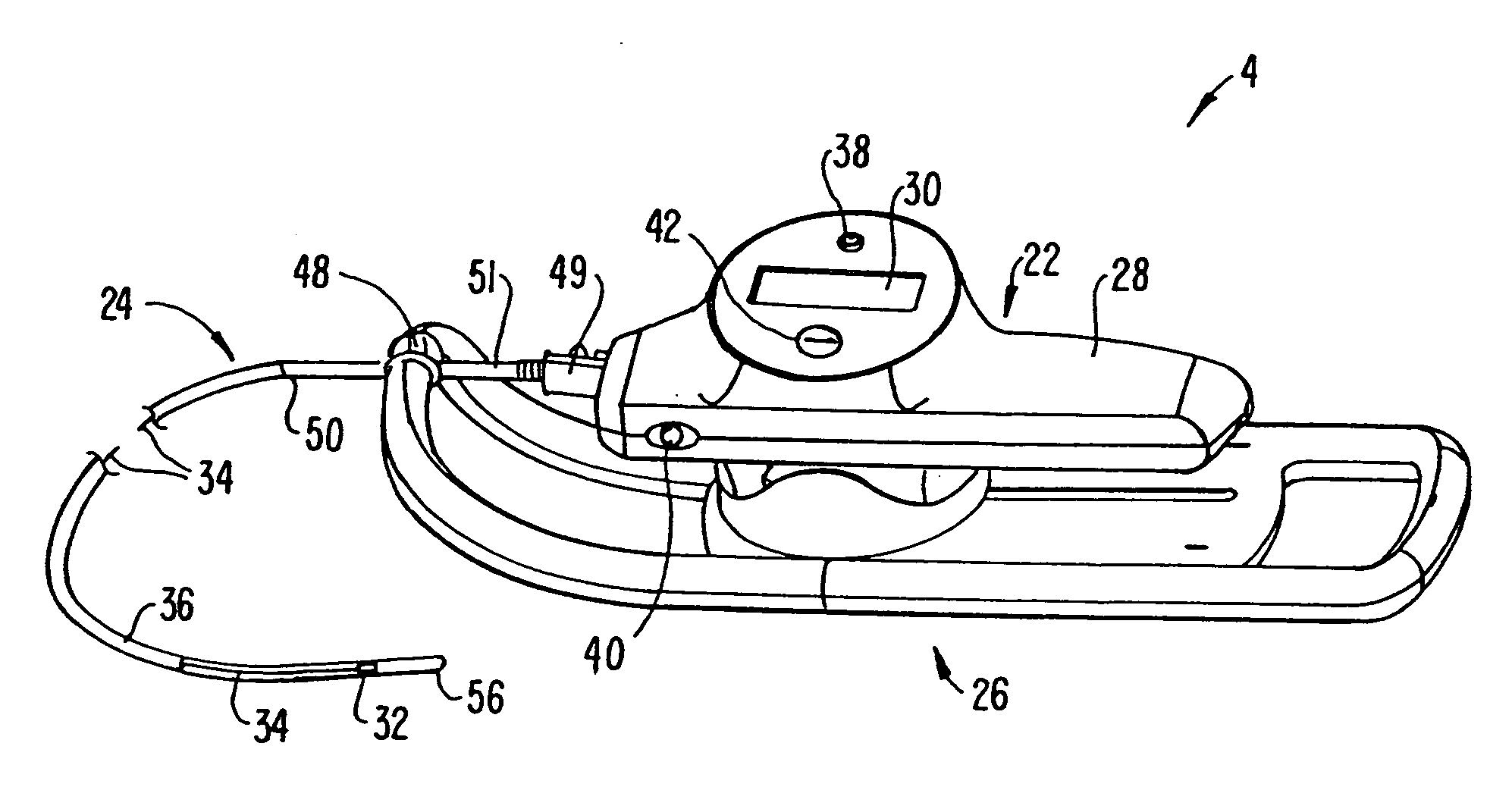
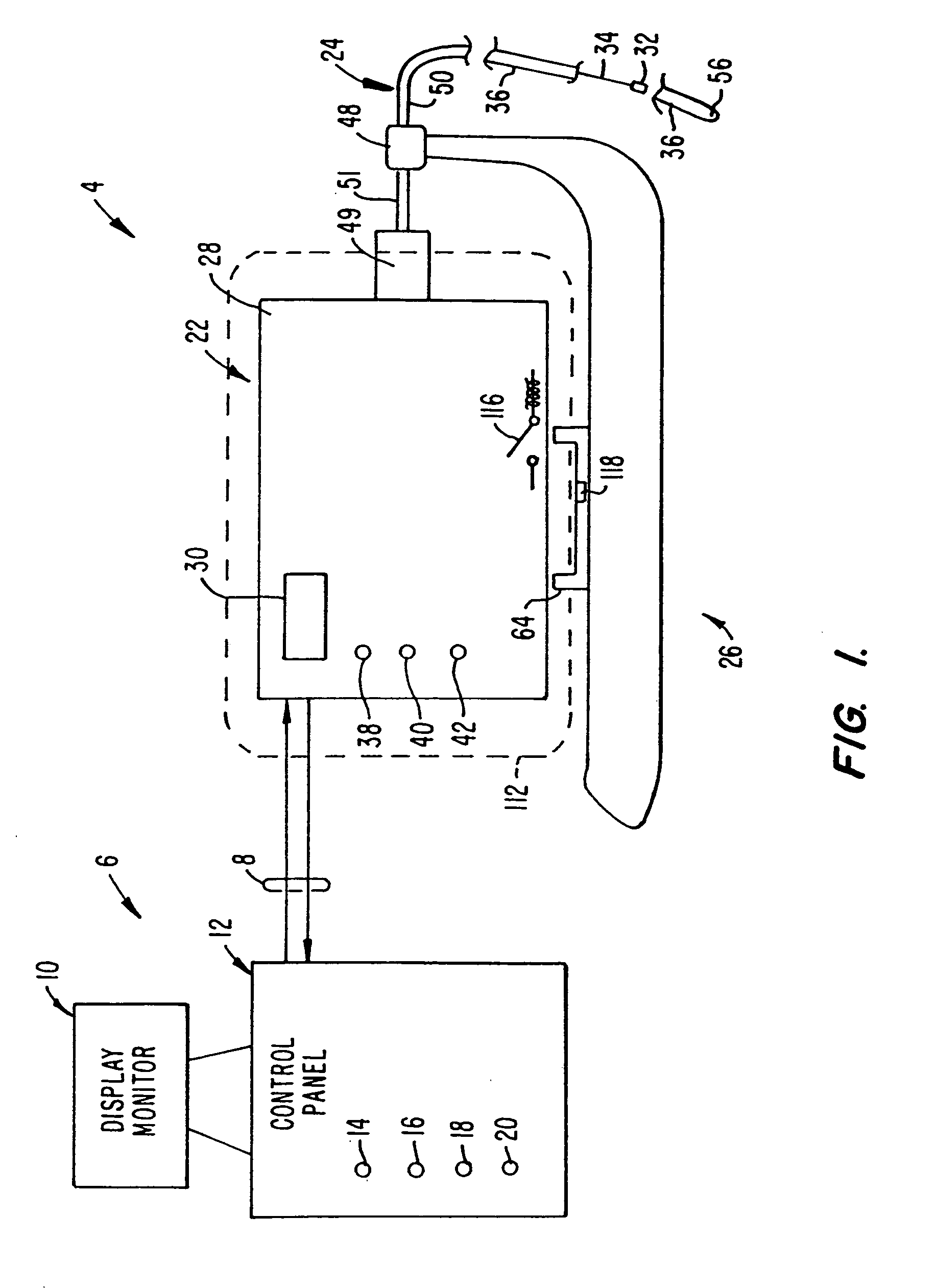
[0027]FIG. 1 schematically illustrates a driveable catheter system 2 made according to the invention. System 2 includes broadly a driveable catheter assembly 4 operably coupled to a control unit 6 through a two-way data and communication link 8. One such two-way communication link includes an RS232 communication link which permits information and data from catheter assembly 4 to be directed to control unit 6 and permits instructions and control signals to be provided to driveable catheter assembly 4 from control unit 6.

[0028] Control unit 6 includes a display monitor 10 providing display of translation displacement information as well as other information. Control unit 6 also includes a control panel 12 which may include, for example, an alphanumeric keyboard, dedicated input buttons or a combination thereof. Other type of inputs including voice command input or a touch screen type of input can also be provided by control unit 6. In particular, control panel 12 provides for rotator...


PUM


Abstract

The system (2) includes a catheter drive unit (22) and a catheter (24) extending therefrom movably mounted to a catheter drive sled (26). The catheter drive unit rotates and translates the catheter core (34) within the catheter sheath (36). The sled has a serrated, conical drive unit interface (82), with a bag-piercing tip (86) mateable with a translator drive output (92) so that a sterile drape (112) enclosing the catheter drive unit is automatically pierced when the catheter drive unit is mounted to the sled. A control unit (6) is spaced apart from the catheter drive unit and provides power and commands to the catheter drive unit and receives information and data from the catheter drive unit. The rotator and translator drive motors (54, 90) are operated from both the control unit and the catheter drive unit. Both the control unit and catheter drive unit have translation displacement displays (10, 30).

Description

CROSS-REFERENCE TO RELATED APPLICATIONS [0001] This is a Continuation-in-part of U.S. patent application Ser. No. 09 / 167,178, filed Oct. 6, 1998, entitled “Driveable Catheter System”, the disclosure of which is incorporated by reference. This is also related to U.S. patent application Ser. No. 09 / 130,198, filed Aug. 5, 1998, entitled “Automatic / Manual Longitudinal Position Translator and Rotary Drive System for Catheters”; U.S. patent application Ser. No. 09 / 047,064, filed May 7, 1998, entitled “Combined Motor Drive and Automatic Longitudinal Position Translator for Ultrasonic Imaging System”; U.S. patent application Ser. No. 08 / 721,433 filed Sep. 27, 1996, entitled “Catheter System and Drive Assembly Thereof”; U.S. patent application Ser. No. 08 / 722,325 filed Sep. 27, 1996, entitled “Device for Controlled Longitudinal Movement of an Operative Element Within a Catheter Sheath and Method”; and U.S. Pat. No. 5,361,768, issued Nov. 8, 1994, entitled “Automated Longitudinal Position Tra...

Claims


Application Information

Patent Timeline
20 Apr 2006
Publication
US20060084911A1
IPC
A61M31/00; A61B1/01; A61B8/12; A61B19/08; A61M25/01
CPC
A61B8/12; A61B8/4209; A61B8/4461; A61B19/081; A61M25/0113; A61M2025/0008; A61B1/0016; A61B46/10
Inventors
BELEF, W. MARTIN; REAM, JOHN H.