Guided ablation with end-fire fiber

a technology of end-fire fiber and ablation apparatus, which is applied in the field of surgical instruments, can solve the problems of reduced physical activity, stroke, atrial fibrillation, and particularly difficult, and achieves the effects of reducing physical activity, and reducing the risk of strok

Inactive Publication Date: 2006-04-20
ENDOPHOTONIX
View PDF98 Cites 59 Cited by
  • Summary
  • Abstract
  • Description
  • Claims
  • Application Information

AI Technical Summary

Problems solved by technology

Atrial fibrillation prevents the heart from pumping blood efficiently causing reduced physical activity, stroke, congestive heart failure, cardiomyopathy and death.
Once these lines scar and heal, they disrupt electrical pathways that may cause atrial fibrillation.
This is particularly difficult when radio frequency (RF) energy is employed because it relies exclusively on thermal diffusion to create transmural lesions i.e, flow of heat from higher to lower temperature.
The cooling effect of blood on the endocardial surface within the atrium limits attainment of the temperature required to form thermal lesions.
Higher temperatures cause boiling of interstitial water creating explosions and subsequent tissue perforations.
Perforations of the atrial wall leads to a weakening of the heart structure as well as significant bleeding during surgery that must be controlled.
Additionally, high electrode / tissue temperatures can create burns and adhesion between the probe and the heart tissue.
Such adhesions can insulate the probe from the heart tissue blocking the efficient application of energy.
These procedures are also a problem for the surgeon and staff who often must stop to clean the tip of the probe.
This approach requires access into the left atrium which adds complexity and increases risk to the patient.
However in this application, the blood warms the tissue at the endocardial surface which again limits the attainment of temperatures required to cause cellular death and create transmural lesions.
As a result, laser ablation is fast and results in narrow lesions.
However, in the prior art, laser ablation for treating atrial fibrillation has been troublesome.
Viola et al. discuss problems associated with the use of laser energy to treat atrial fibrillation.
These concerns are directed to safety and reliability and note that lasers are prone to overheating because of the absence of a self-limiting mechanism.
The authors note that over-heating with lasers can lead to crater formation and eventually to perforation, especially when using pin-tip devices.
The authors note that the high power of laser ablation (described as 30 to 80 Watts) results in the laser technique not being widely clinically applied.
The mechanical effects resulting from direct heating of the myocardial tissue with laser energy results in cellular explosions caused by shock waves.
A coring of the myocardium by a laser could result in a full wall thickness perforation and resulting leakage of blood.
This reduces the longitudinal movement required to produce linear lesions but, by decreasing the coherency of the laser beam before entering cardiac tissue, and negates many of the advantages of light to more deeply penetrate cardiac tissue.
Reducing energy penetration depths increases the risk (particularly on a beating heart) of creating a lesion that is less than transmural.
A further difficulty with creating linear nonconductive lesions is the inability to verify that a truly nonconductive lesion has been produced.
If a transmural lesion is not properly formed in accordance with the Maze procedure, the treatment for atrial fibrillation may not be successful.

Method used


Image

  • Guided ablation with end-fire fiber
  • Guided ablation with end-fire fiber
  • Guided ablation with end-fire fiber

Examples


Embodiment Construction

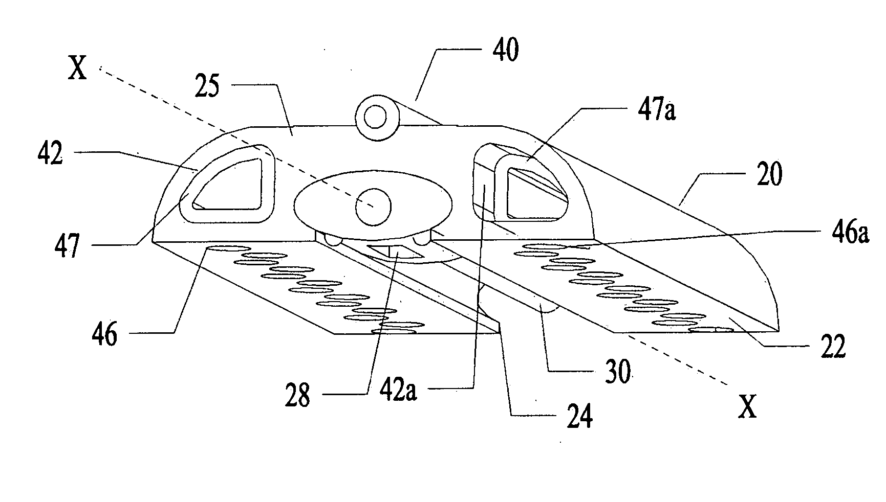
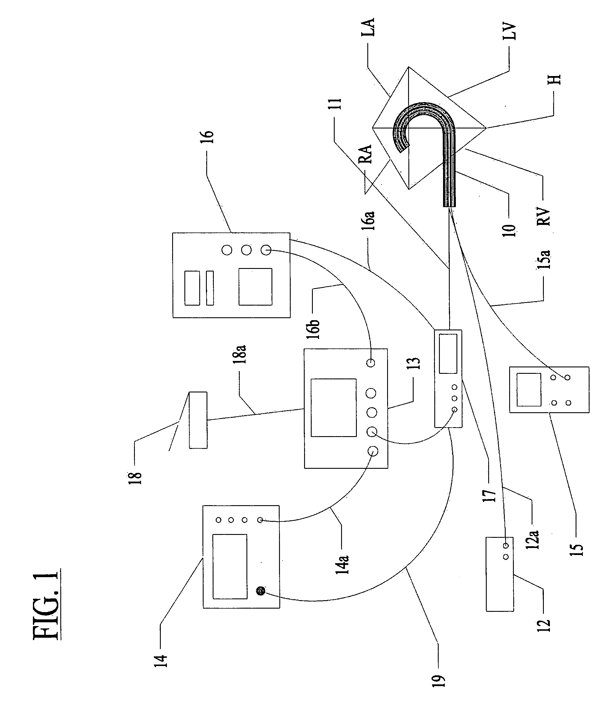
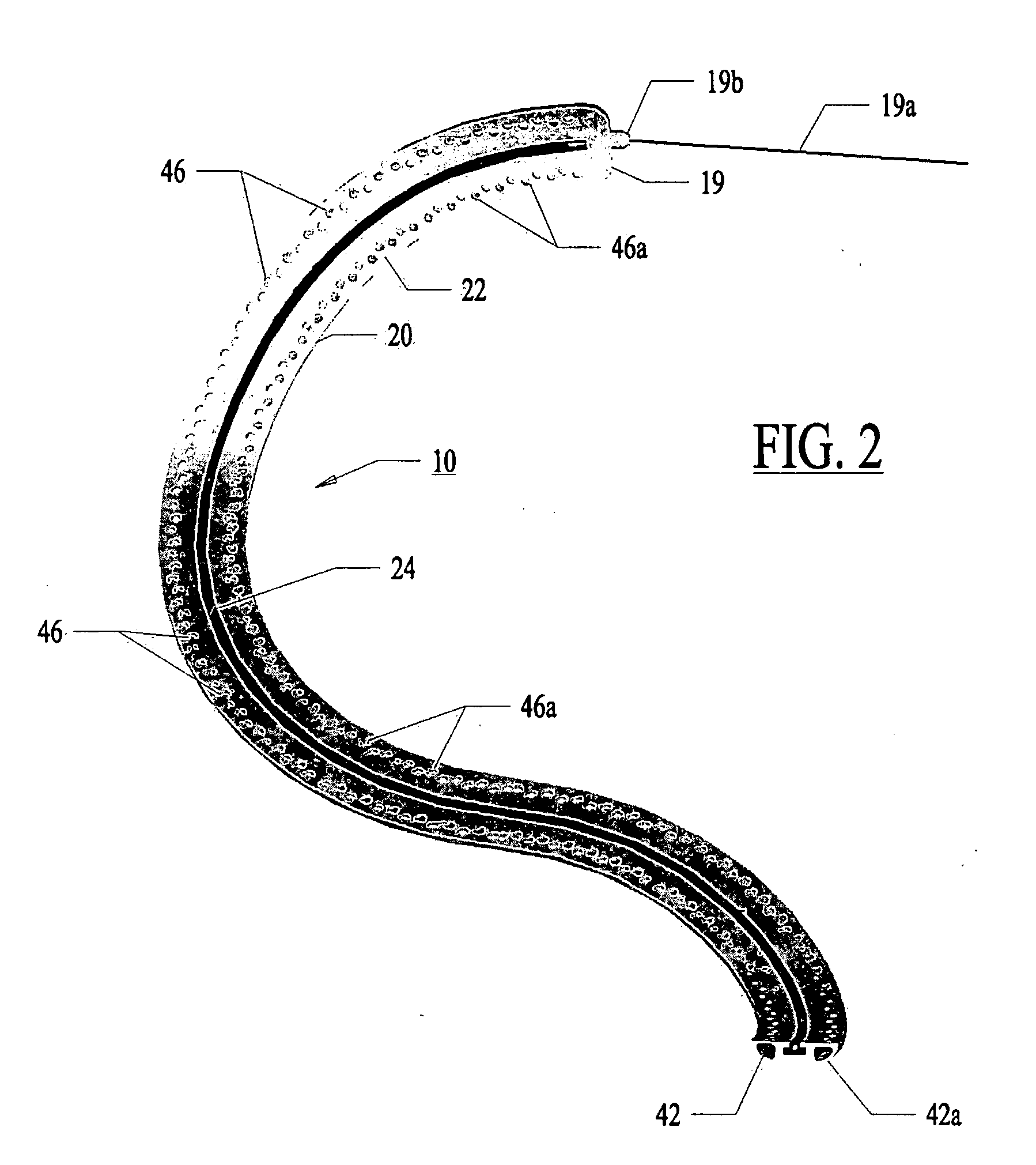
[0074] Referring now to the several drawing figures in which identical elements are numbered identically throughout, a description of a preferred embodiment of the present invention will now be provided. In the preferred embodiment, the invention is described as a lesion formation tool for applying laser energy to the epicardial surface of the heart to create a transmural ablation line along the heart. As used in this application, the term “ablation” is used in the context of creating necrosed tissue in the myocardium while avoiding tissue perforation or removal. In the following description, a guide member is described for guiding a lesion formation tool in a MAZE pattern. It will be appreciated the teachings of the present application could be applied to other types of ablation tools (e.g., RF ablation, ultrasound or other). Also, this application may refer to a lesion as “linear”. The use of “liner” is not meant to be limited to a straight line but is intended to include a curved...


PUM


Abstract

A method and apparatus for treating a body tissue in situ (e.g., an atrial tissue of a heart to treat atrial fibrillation) include a lesion formation tool is positioned against the heart surface. The apparatus includes a guide member having a tissue-opposing surface for placement against a heart surface. The guide member also has interior surfaces and a longitudinal axis. A guide carriage is sized to be received with the guide member and moveable therein along the longitudinal axis. An optical fiber is positioned within the guide carriage with the carriage retaining the fiber. The carriage receives the fiber with an axis substantially parallel to the longitudinal axis and bends the fiber to a distal tip with an axis of said fiber at said distal tip at least 45 degrees to the longitudinal axis and aligned for discharge of laser energy through the tissue opposing surface.

Description

I. CROSS-REFERENCE TO RELATED APPLICATION [0001] This patent application is a continuation-in-part application of U.S. patent application Ser. No. 11 / 102,091 filed Apr. 8, 2005 titled “Apparatus And Method For Guided Ablation Treatment” (published Aug. 18, 2005 as U.S. patent application Publication No. US 2005 / 0182392 A1 and incorporated herein by reference). The '091 patent application is a continuation-in-part application of U.S. patent application Ser. No. 10 / 975,674 filed Oct. 28, 2004 titled “Apparatus and Method for Laser Treatment” (published May 5, 2005 as U.S. patent application Publication No. US 2005 / 0096643 A1 and incorporated herein by reference). The '674 application claims priority to U.S. Provisional Patent Application Ser. No. 60 / 516,242 with an assigned filing date of Oct. 30, 2003.II. BACKGROUND OF THE INVENTION [0002] 1. Field of the Invention [0003] The present invention relates to surgical instruments for laser cardiac ablation procedures. More particularly, t...

Claims


Application Information

Patent Timeline
Patent Type & Authority Applications(United States)
IPC IPC(8): A61B18/18A61B17/00A61B18/22
CPCA61B5/053A61B5/0538A61B5/117A61B18/20A61B18/22A61B18/24A61B2017/00026A61B2017/00243A61B2017/00247A61B2017/0243A61B2017/306A61B2017/3488A61B2018/00196A61B2018/00392A61B2018/00636
Inventor MESTER, DANA RAYGRACE, KENNETH WAYNEBRUCKER, GREGORY G.SAVAGE, STEVEN D.
Owner ENDOPHOTONIX
Why Eureka
Try Eureka