Implants and methods for treating bone

a technology of implants and bone, applied in the field of filamentlike implants, can solve the problems of fractures in the spine and hips, affecting mobility and quality of life, and the medical advances aimed at slowing or arresting bone loss from aging have not provided solutions to this problem

Inactive Publication Date: 2006-04-20
DFINE INC
View PDF50 Cites 177 Cited by
  • Summary
  • Abstract
  • Description
  • Claims
  • Application Information

AI Technical Summary

Benefits of technology

[0021] In another aspect of the invention, an introducer sleeve is configured with anchoring means comprising threads for engaging

Problems solved by technology

Medical advances aimed at slowing or arresting bone loss from aging have not provided solutions to this problem.
Osteoporosis affects the entire skeleton but most commonly causes fractures in the spine and hip.
Spinal or vertebral fractures also have serious consequences, with patients suffering from loss of height, deformity and persistent pain which can significantly impair mobility and quality of life.
Osteoporosis describes a condition of decreased bone mass that leads to fragile bones which are at an increased risk for fractures.
In an osteoporotic bone, the sponge-like cancellous bone has pores or voids that increase in dimension, making the bone very fragile.
In an elderly patient, bone resorption can surpass bone formation thus resulting in deterioration of bone density.
The bilateral transpedicular approach is typically used because inadequate PMMA infill is achieved with a unilateral approach.
Since the PMMA needs to be forced into cancellous bone, the technique requires high pressures and fairly low viscosity cement.
Since the cortical bone of the targeted vertebra may have a recent fracture, there is the potential of PMMA leakage.
Leakage of PMMA during vertebroplasty can result in very serious complications including compression of adjacent structures that necessitate emergency decompressive surgery.
The exothermic reaction of PMMA carries potential catastrophic consequences if thermal damage were to extend to the dural sac, cord, and nerve roots.
Vertebroplasty patients often return with new pain caused by a new vertebral body fracture.
Leakage of ceme

Method used


Image

  • Implants and methods for treating bone
  • Implants and methods for treating bone
  • Implants and methods for treating bone

Examples


Embodiment Construction

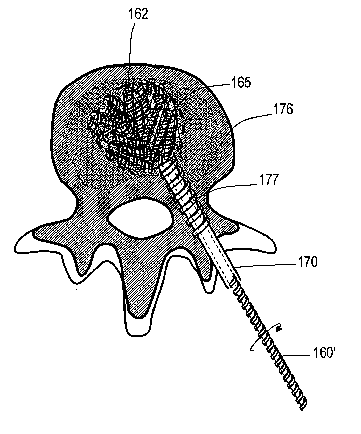
[0042] The present invention relates to implants and methods for treating bone abnormalities such as a vertebral fracture. More specifically, the invention is directed to a porous biocompatible metal or composite scaffold that has pores of a selected dimension, including scaffold ligaments that can have nanoscale pores. The implant can further have a very high modulus or a gradient in modulus. The novel material is suited for several orthopedic applications including treatment of compression fractures, spine fusion and joint replacement procedures.

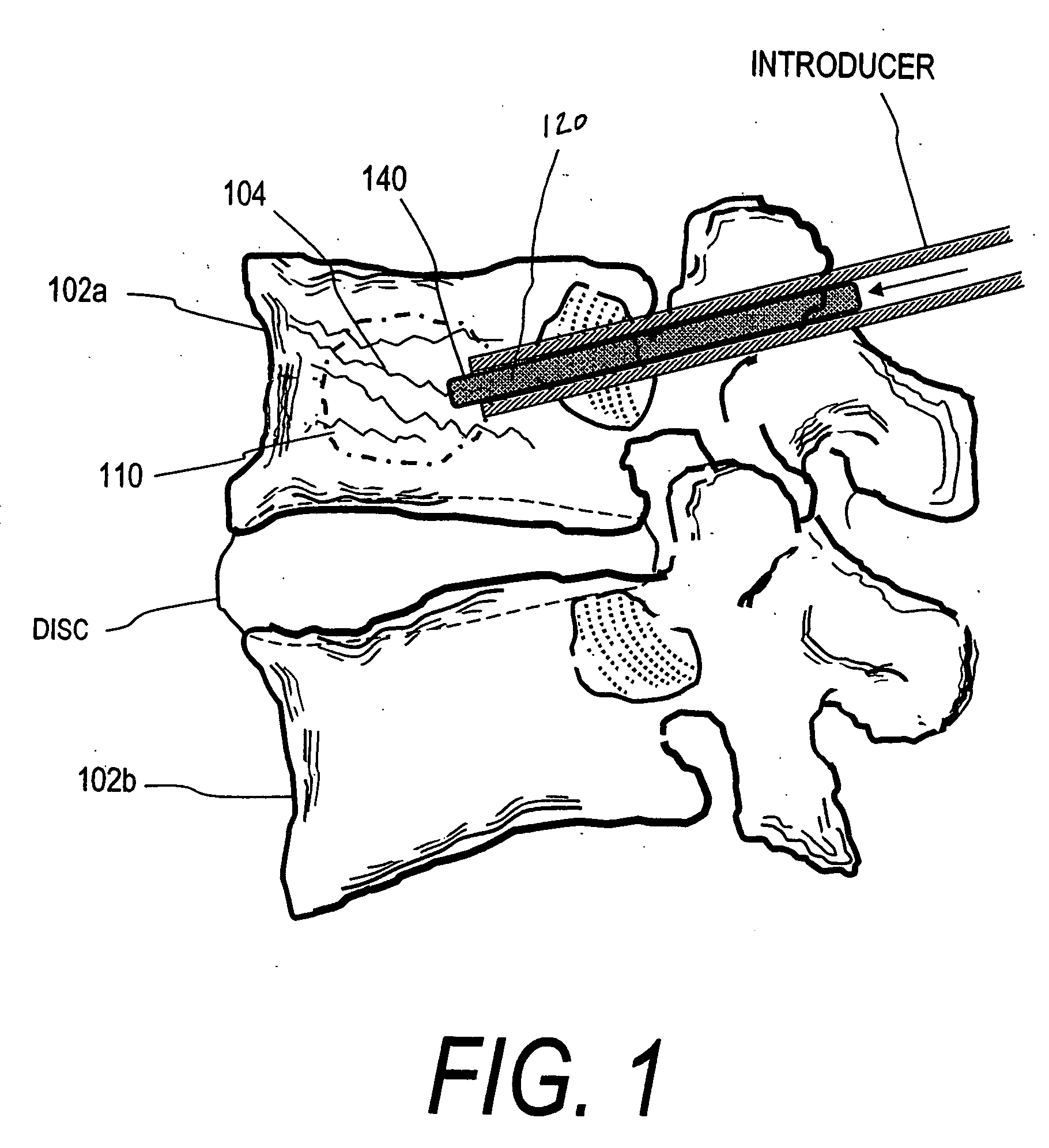
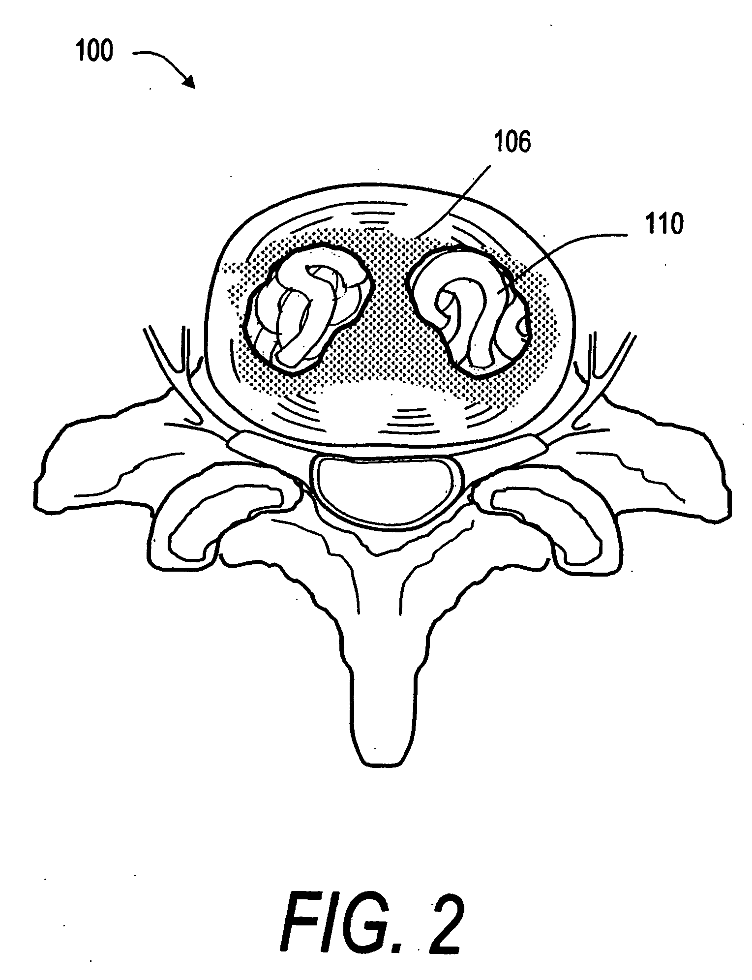
[0043]FIG. 1 shows a spine segment 100 in a patient with an osteoporotic vertebra 102a that is susceptible to a compression fracture 104. The cancellous bone in the interior of the vertebra can fracture and collapse. The targeted treatment site is indicated at 110. The targeted site or sites 110 as indicated in FIG. 2 can be supported by direct injection of at least one deformable filament 120 corresponding to the invention under suitable...


PUM


Abstract

This invention relates to biomedical implants for filling, supporting or treating bone. In one embodiment, the implant comprises an electrospun polymer scaffold that is thereafter plated with a metal to provide a selected high modulus. Such an implant can be fabricated with a selected porosity for tissue ingrowth. The implant can be further provided with a varied modulus along the length of the implant body for inducing bending of the implant for packing in a bone. In another embodiment, the implant is fabricated in an elongated configuration for introducing into bone to treat a vertebral fracture. In another embodiment, the implant can be configured with helical threads for helically driving the implant into a bone.

Description

CROSS-REFERENCE TO RELATED APPLICATIONS [0001] This application claims benefit of Provisional U.S. Patent Application Ser. No. 60 / 600,012 filed Aug. 9, 2004 titled Orthopedic Scaffold Implants, Methods of Use and Methods of Fabrication. This application also is related to the following Provisional U.S. Patent Applications: Ser. No. 60 / 590,588 filed Jul. 16, 2004 titled Orthopedic Scaffold Implants, Methods of Use and Methods of Fabrication; Ser. No. 60 / 590,597 filed Jul. 23, 2004 titled Orthopedic Scaffold Implants, Methods of Use and Methods of Fabrication; and Ser. No. 60 / 590,598 filed Jul. 23, 2004 titled Orthopedic Scaffold Implants, Methods of Use and Methods of Fabrication. The entire contents of all of the above cross-referenced applications are hereby incorporated by reference in their entirety and should be considered a part of this specification.BACKGROUND OF THE INVENTION [0002] 1. Field of the Invention [0003] This invention relates to filament-like implants for filling ...

Claims


Application Information

Patent Timeline
IPC IPC(8): A61F2/34
CPCA61B17/70A61B17/7094A61F2/08A61F2/30771A61F2/30965A61F2/442A61F2002/30014A61F2002/30069A61F2002/30909A61F2002/4495A61F2250/0018A61L27/04A61L27/14A61L27/56A61L2430/38
Inventor TRUCKAI, CSABASHADDUCK, JOHN H.
Owner DFINE INC
Why Eureka
Try Eureka