
Electrical implants

Inactive Publication Date: 2006-04-20
FRITSCH MICHAEL H
View PDF61 Cites 46 Cited by
  • Summary
  • Abstract
  • Description
  • Claims
  • Application Information

AI Technical Summary

Benefits of technology

[0017] In accordance with the above and other objects of the invention, energy is radiated through the unbroken skin to an implanted transducer that converts it to non-radiant electrical energy. In one embodiment, the energy is stored in batteries for powering implanted electrical apparatuses, but it may be directly applied to an implant. In the preferred embodiment, the radiant energy is electromagnetic energy at frequencies high enough to be substantially straight line in transmission and attenuated quickly so that there is no substantial difficulty in avoiding interference with biological processes, such as the rhythm of the heart, nor of implanted devices, such as pacemakers. Preferably, the transducer is photovoltaic and the electromagnetic energy is in the light wavelength range. Feedback signals may be provided such as for example by light emitting devices, such as LEDs or fluorescent devices or by converting the signals to low intensity a.c. signals for transmission through the skin, to provide data such as the intensity of the radiation that is contacting the photovoltaic device or to indicate the state of charge of the batteries or the condition of the implant or the like.
[0019] Signals may be transmitted through the skin from inside the patient to an external apparatus without a break in the skin using wavelengths within the same general range of wavelengths of electromagnetic energy, but preferably spaced from the range used for transmitting energy into the body to avoid interference between the two.
[0021] From the above description, it can be understood that the method and apparatus for supplying power to implants of this invention has several advantages: (1) it transmits energy through the skin without an opening in the skin with no substantial risk of interference with other electrically operated implants or biological processes; (2) it is not subject to misfiring or damage from external electromagnetic signals such as emanate from electric motors, radio transmitters, power lines and the like; and (3) it is sufficiently thin and flexible to permit ready implantation in patients.

Problems solved by technology

This prior art type of apparatus and methods for supplying power and control signals has several disadvantages such as for example: (1) they may induce currents unintentionally in metallic parts of other implants or trigger other biological responses; and (2) they may receive interference signals on the receiving coil that disrupt control of or overload circuitry.

Method used


Image

  • Electrical implants
  • Electrical implants
  • Electrical implants

Examples


Embodiment Construction

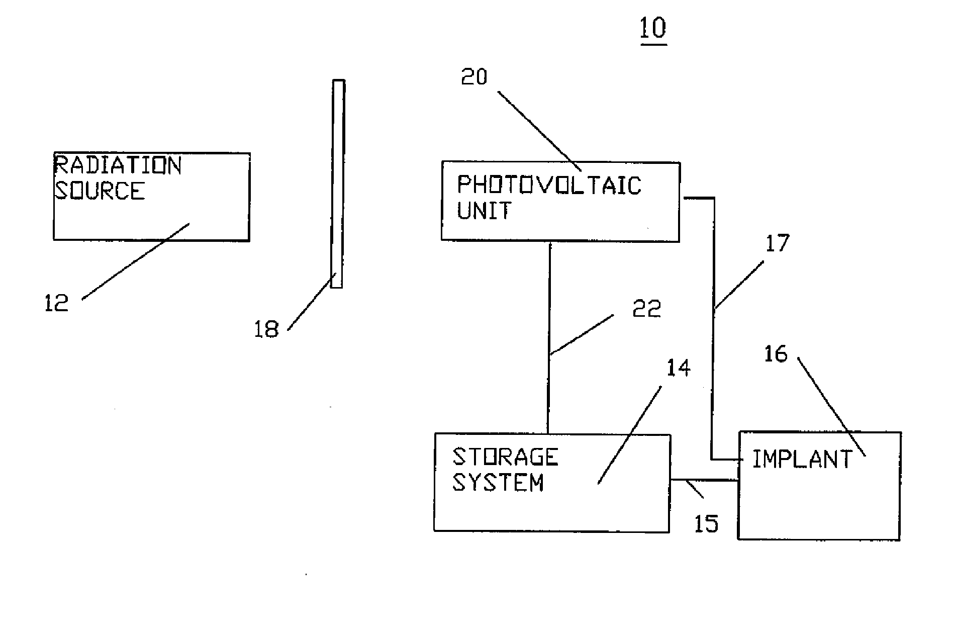
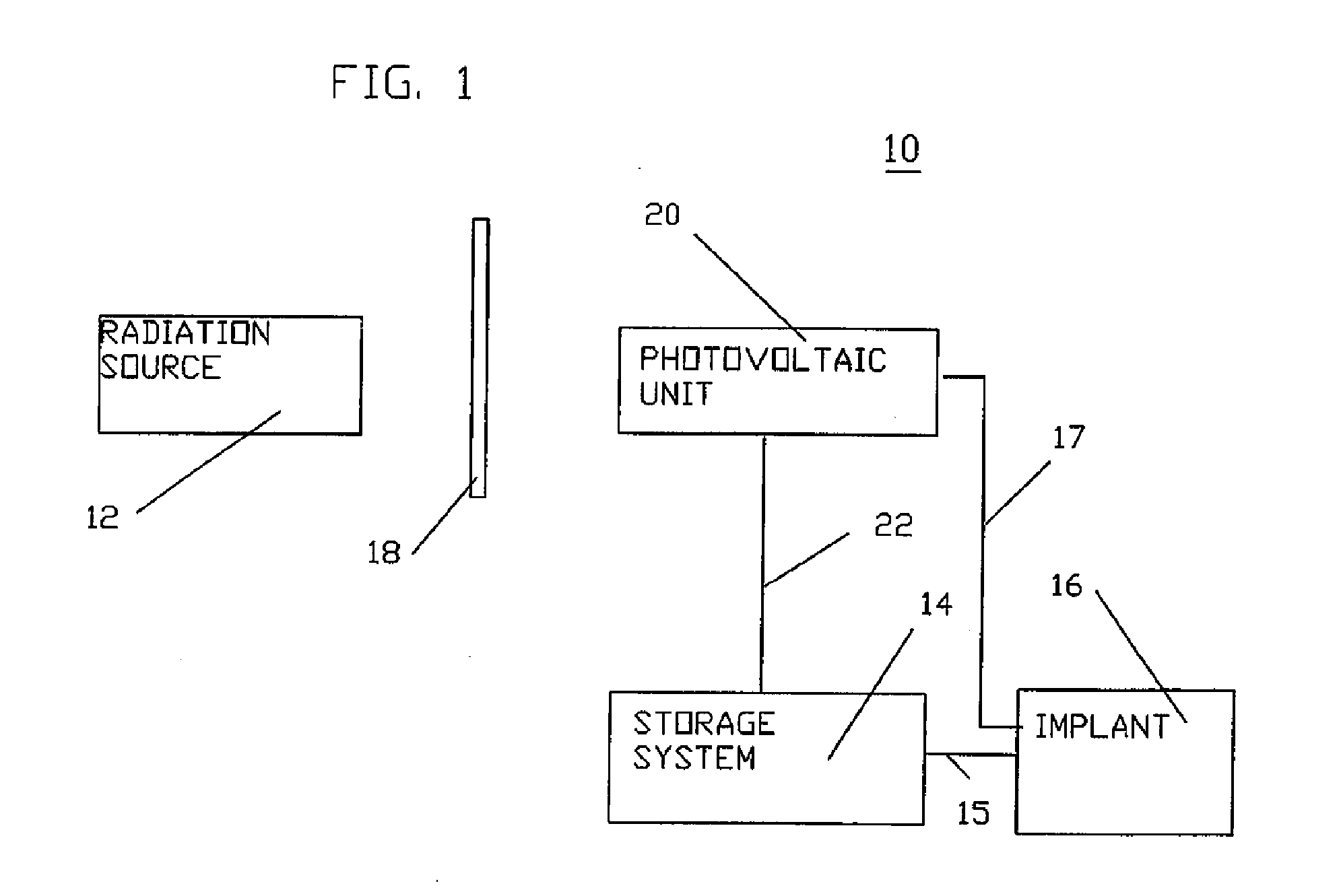
[0034] In FIG. 1, there is shown a block diagram of apparatus 10 for transcutaneously transmitting energy through the tissue 18 of a patient to an implant 16, which apparatus 10 includes a radiation source 12, a photovoltaic unit 20 and an energy storage unit 14. As shown in FIG. 1, the radiation source 12 transmits energy through the unbroken skin or deeper tissues 18 to the photovoltaic unit 20, which generates current in response to the radiation and transmits it through a shielded conductor 22 to the storage system 14. The storage system 14 stores energy for application to the implant 16 and transmits signals back to the photovoltaic unit 20 over one or more conductors 22. The implant 16 receives energy and control signals over one or more conductors 15 and transmits signals relating to its condition over conductor 17.

[0035] While many photovoltaic systems are available including photodiode arrays of several types, flexible thin film photovoltaic systems are preferred. They sho...


PUM


Abstract

An external module is mounted to a person and transmits energy in the light spectrum through the skin to an internal module which converts it to d.c. current with a film photocell. The d.c. current can be used to charge batteries for powering an implant without a break in the skin and to power an implant directly. Light signals can also be transmitted through the skin from an internal module to the external module to monitor implants, battery charging equipment, batteries and patient functions. Control signals can be transmitted from the external module to the internal module. The energy may be in the wavelength range of 1×10⁻⁴ to 1×10⁻⁹ meters and preferably in the wavelength range of 4×10⁻⁷ to 8×10⁻⁷ meters.

Description

BACKGROUND OF THE INVENTION [0001] This invention relates to apparatus and methods for supplying energy to electrically operated implants. [0002] It is known to transcutaneously supply power and control signals to electrically operated implants in animals and most commonly in humans. One type of known apparatus for supplying power to such devices transmits the power and / or control signals through the skin as electromagnetic energy to avoid breaking the skin. In some such apparatuses, the energy is stored in implanted storage batteries that supply power to battery-operated implants. [0003] In some prior art systems of this type, alternating current from an external source is induced in an implanted receiving coil and conducted to the storage battery or batteries or transmitted directly to the electrically operated implant. Prior art systems of this type are disclosed in U.S. Pat. Nos. 6,525,512; 6,227,204; 6,073,050 and 5,411,537. [0004] This prior art type of apparatus and methods f...

Claims


Application Information

Patent Timeline
IPC IPC(8): A61N1/08
CPCA61B2560/0219A61N1/3787
Inventor FRITSCH, MICHAEL H.
Owner FRITSCH MICHAEL H
Learn More