Method and means for electrical stimulation of cutaneous sensory receptors

a technology of electrical stimulation and sensory receptors, which is applied in the field of electrode plates for electrical stimulation of cutaneous sensory receptors, can solve the problems of high threshold current needed to activate c fibers, unsuitable for stimulation of unmyelinated fibers classified as c fibers, and inability to tolerate, so as to increase the pressure on the electrodes, and speed up the healing of skin wounds.

Active Publication Date: 2006-04-20
MEAGAN MEDICAL
View PDF36 Cites 92 Cited by
  • Summary
  • Abstract
  • Description
  • Claims
  • Application Information

AI Technical Summary

Benefits of technology

[0037] It is preferred for the mounting to comprise a step in which the means is pressed against the skin by applying a force to its face opposite to the stimulation face, thereby temporarily flattening the means and allowing portions of the skin surface to contact an adhesive provided in depressions of the stimulation face. Upon release of the pressure, the means for administration of electrical stimuli seeks to assume its original configuration, thereby increasing the pressure on the electrodes for intracutaneous administration.
[0038] The electrode plate of the invention has multiple uses, such as the activation of endogenous mechanisms that inhibit pain and itch in patients. The electrode plate enables a precise stimulation of the receptors that are related to the painful or itchy tissue; the increase of vascularisation of the skin for cosmetic purposes or speed up the healing of skin wounds; The treatment of animals that for different reasons cannot take drugs, such as horses or dogs that participate in competitions; in research, by allowing electrical stimulation of any combination of sensory input and for studying interactions between different sensory channels in the central nervous system.

Problems solved by technology

TENS is, however, not suitable for the stimulation of unmyelinated fibers classified as C fibers.
Using TENS, the threshold current needed to activate C fibers is very high and thus cannot be tolerated.
CFS allows topographically restricted and tolerable electrical stimulation of thin (Aδ and C) cutaneous fibers but is not useful for the stimulation of Aβ fibers.
In these cases there are no means of controlling skin indentation other than the length of the needles.
Due to the fact that most body parts are curved; such electrode plates usually do not allow controlled skin penetration of multiple needle electrodes to a defined skin depth.
There is, however, no known method that combines an effective stimulation of Aβ fibers at multiple plates and in a tolerable way, with consecutive stimulation of Aδ / C fibers with a pattern of needle-like electrodes within a defined skin area.
Moreover, there is no known method to combine TENS and CFS in one treatment.
While being tolerable it is initially uncomfortable and this may reduce compliance in children and persons with sensitive skin.
Existing techniques have no solution to this problem other than a gradual increase in stimulation intensity.
Known devices for cutaneous Aδ / C fiber stimulation are not easily applied to the skin.
In some situations this is impractical and thus reduces patient compliance.
Known methods for multi-channel electrode stimulation of Aδ / C fibers use an electrode plate that does not allow moisture from the skin area covered by the plate to evaporate.
This results in accumulation of moisture between the plate and the skin.
This arrangement decrease the precision with which the length of the protruding electrode tips are made during manufacture.
As it is important to control the depth in the skin, this is a clear disadvantage.

Method used


Image

  • Method and means for electrical stimulation of cutaneous sensory receptors
  • Method and means for electrical stimulation of cutaneous sensory receptors
  • Method and means for electrical stimulation of cutaneous sensory receptors

Examples


example 1

Embodiments of the Electrode Plate of the Invention

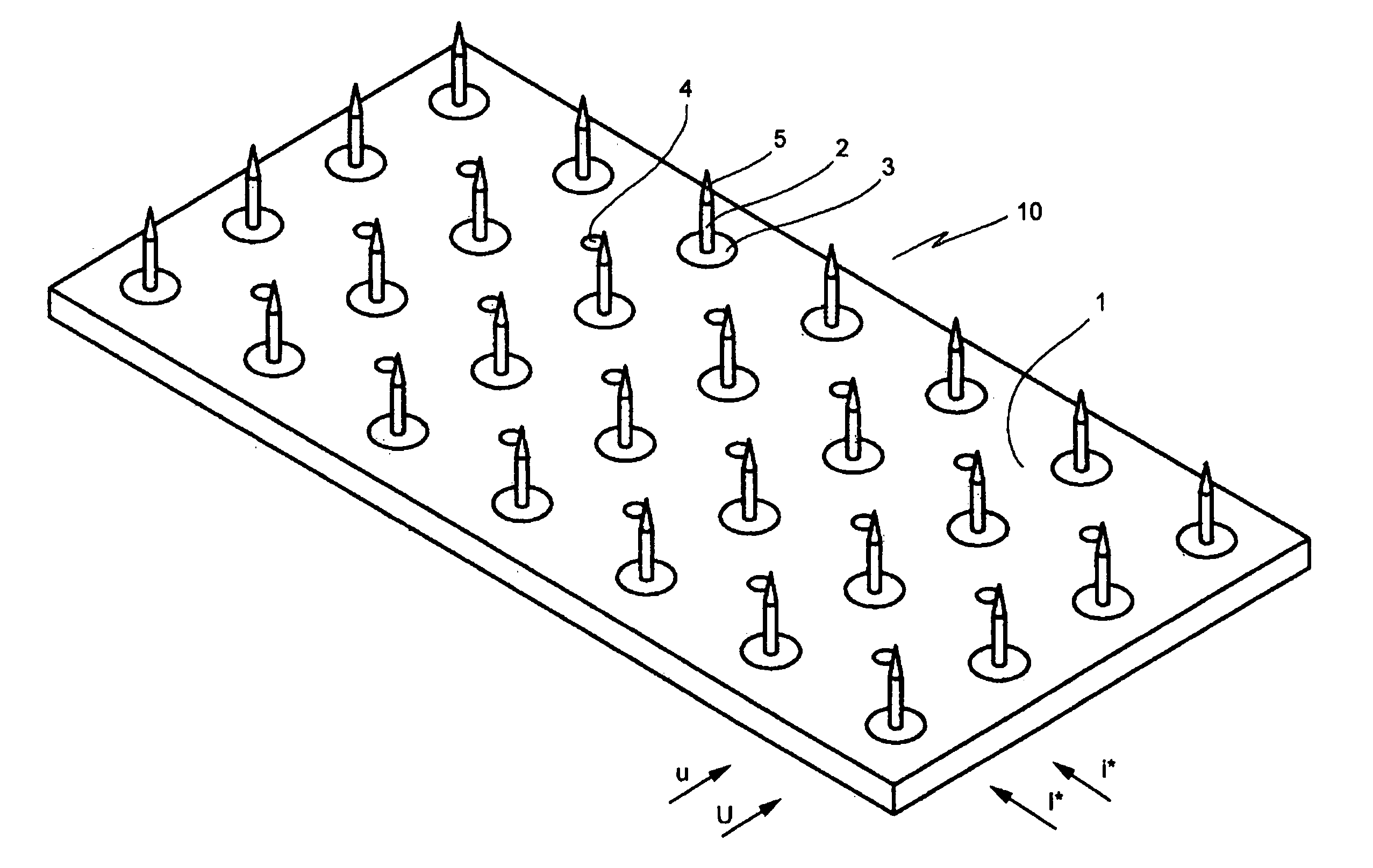
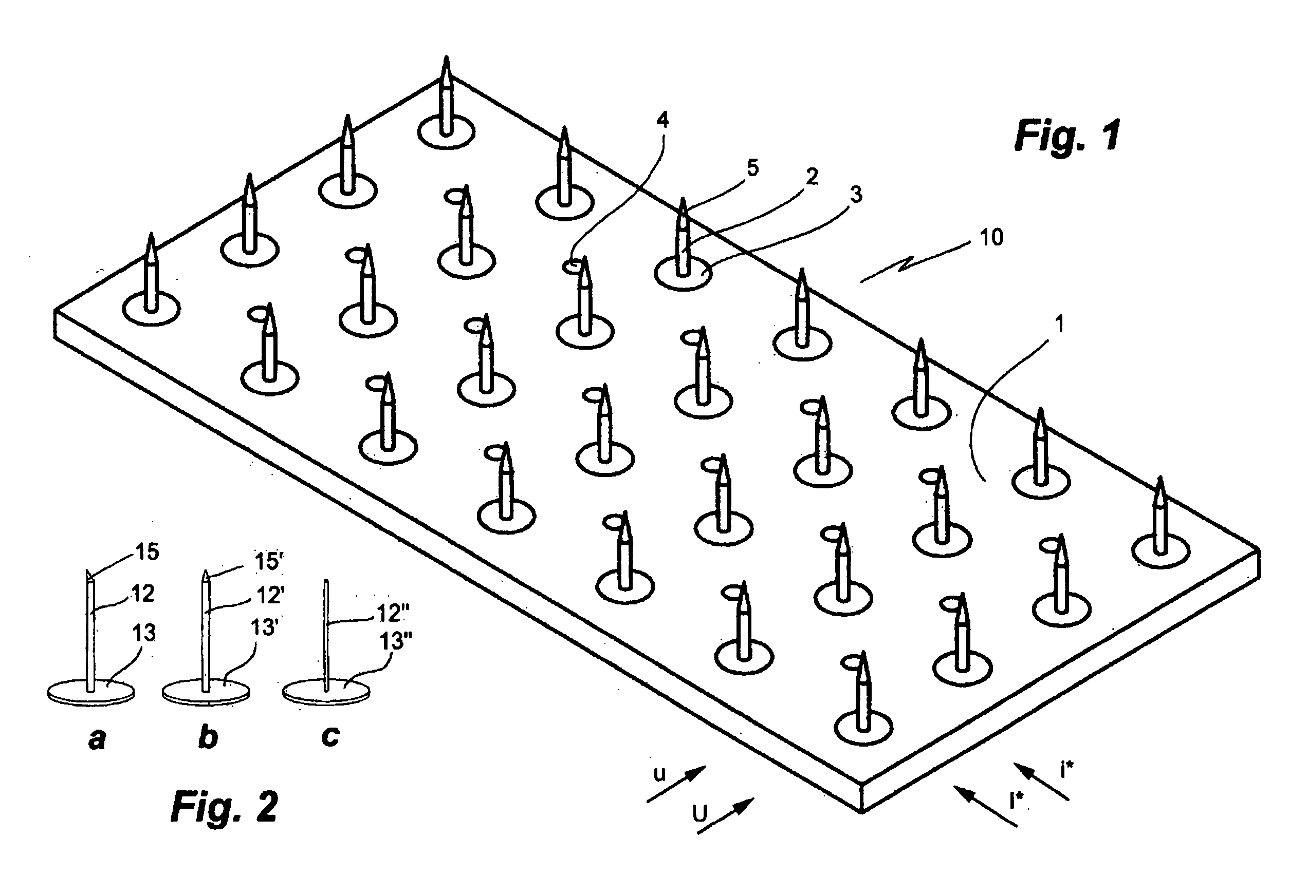
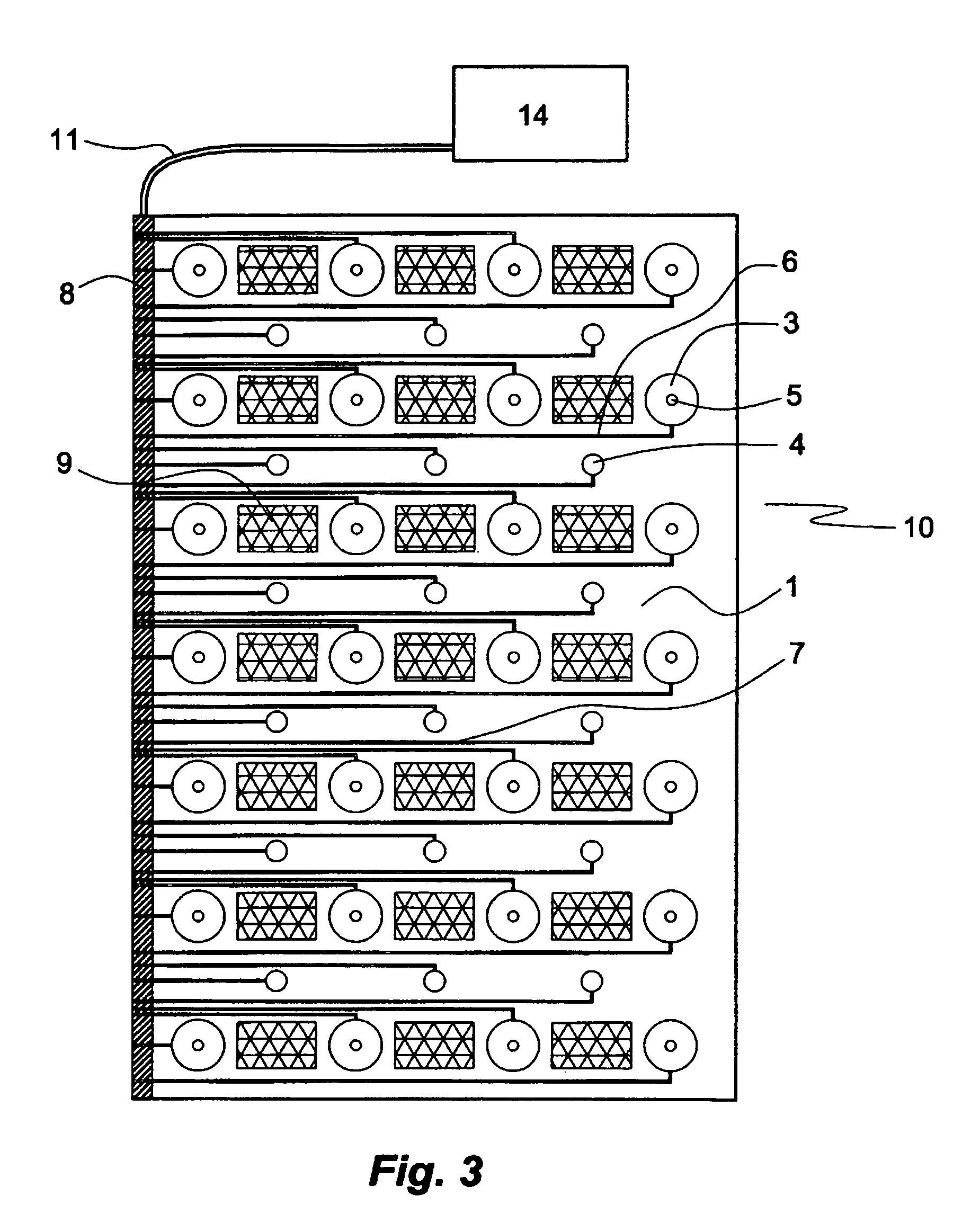
[0053] A first embodiment of the electrode plate of the invention is illustrated in FIGS. 1 and 3. The flat electrode plate 10 comprises a plate element 1 of a polymer material carrying, on its front face, a rectangular array of NL electrodes 2, 3, 5, each comprising a base 3 and an electrode element 2 with a pointed tip 5, and CP electrodes 4, in which rows U, etc., cf FIG. 6, four NL electrodes 2, 3, 5, are interspaced with rows u, etc., cf FIG. 6, of CP electrodes 4, each comprising three electrodes, in a manner that each CP electrode 4 is equidistant from two pairs of NL electrodes 2, 3, 5 in neighboring rows. To provide for consecutive stimulation rows or columns of NL and CP electrodes can be electrically coupled but it is equally possible to independently stimulate any desired combination of electrodes of the same kind and even each individual electrode (FIG. 3) by arranging corresponding electrical connections, such as in f...

example ii

Control of the Electrode Plate by Stimulator

[0071] In one embodiment of the invention electrically conductive straps, bonded to a thin and flexible sheet of for example polyester, are used to connect the CP and / or NL electrodes to a multi-channel stimulator. These straps are electrically insulated, by e.g. a plastic non-conductive film, except at the contact places for the electrodes and the multi-channel stimulator. In another embodiment, thin electrically conducting wires attached to the electrode plate of the invention are used to connect the CP and / or NL electrodes with a stimulator. The straps or wires are electrically insulated except at their free ends disposed at a circumferential side wall of electrode plate for easy connection with an external multi-channel stimulator (stimulating unit).

[0072] In a preferred embodiment the adhesive patches are made of electrically conductive material. The adhesive patches are then in contact with the CP electrodes on the plate which are,...

example 3

Venting Perforations

[0073] The electrode plate of the invention of polymer material can be provided with perforations providing communication between its front and rear faces to allow moisture exuded from the skin to evaporate. Preferably from 1% to 30% of surface of the front and rear faces are covered by the perforations. Alternatively, the polymer material from which the main structure of the electrode plate is made, such as polyurethane with open pores, is permeable to water vapour.


PUM


Abstract

Electrode plate comprising a stiff or flexible electrically non-conductive plate element having a front face and a rear face and a pattern of needle-like (NL) electrodes for electrical stimulation of cutaneous thin Aδ/C fibers and conductive plate (CP) electrodes for electrical stimulation cutaneous large Aβ fibers disposed on the front face.

Description

CROSS-REFERENCE TO RELATED APPLICATION [0001] This application claims the benefit of U.S. Provisional Application No. 60 / 624,500 filed Oct. 19, 2005, which is incorporated herein by reference.FIELD OF THE INVENTION [0002] The invention relates to an electrode plate for electrical stimulation of cutaneous sensory receptors, in particular for patterned stimulation of cutaneous Aβ fibers and cutaneous Aδ / C fibers within defined skin areas for the relief of itch, pain and other medical or animal care or cosmetic purposes, and to a corresponding use and method of treatment. BACKGROUND OF THE INVENTION [0003] In the skin, different sensory qualities interact competitively with one another (Schmidt R F (1971). Presynaptic inhibition in the vertebrate central nervous system. Ergebn. Physiol. 63:20-101; Melzack R et al. (1965). Pain mechanisms: a new theory. A gate control system modulates sensory input from the skin before it evokes pain perception and response. Science 150: 971-979; McMaho...

Claims


Application Information

Patent Timeline
Patent Type & Authority Applications(United States)
IPC IPC(8): A61N1/04A61B5/296
CPCA61N1/0456A61N1/0468A61N1/0476A61N1/0502A61N1/36021A61H39/002A61H39/00A61N1/32
Inventor SCHOUENBORG, JENS OLAF ROE
Owner MEAGAN MEDICAL
Why Eureka
Try Eureka