Systems and methods for a disaster recovery system utilizing virtual machines running on at least two host computers in physically different locations

a disaster recovery system and virtual machine technology, applied in the field of virtual machines, can solve the problems of incompatibility between the instruction set used by the intel 80x86 processor family and the instruction set used by the powerpc processor family, requiring generally many clock cycles to execute, and incompatibility among the other elements of the hardware architecture of the computer system

Active Publication Date: 2006-04-20
MICROSOFT TECH LICENSING LLC
View PDF15 Cites 185 Cited by
  • Summary
  • Abstract
  • Description
  • Claims
  • Application Information

AI Technical Summary

Benefits of technology

[0014] Various embodiments of the present invention are directed to systems and methods for low-cost storage and recovery of the state of a first computer system (a “production host”) using a second computer system (a “backup host”) with minimal disruption to users of said computer system. More specifically, various embodiments of the present invention are directed to providing a software service that is minimally-interrupted by hardware- or software-based disaster events.

Problems solved by technology

As an example, the instruction set used by the Intel 80X86 processor family is incompatible with the instruction set used by the PowerPC processor family.
CISC processors use a large number of instructions, some of which can perform rather complicated functions, but which require generally many clock cycles to execute.
The uniqueness of the processor family among computer systems also typically results in incompatibility among the other elements of hardware architecture of the computer systems.
However, from a cost perspective—that is, the relative costs of utilizing a state recovery system versus the incurred costs of downtime stemming from a disaster—an enterprise will naturally choose the lower-cost option and, as part of this analysis, the cost of a state recovery system must include the cost for upgrades.
If the cost of system upgrades is too high, then the cost of a state recovery system may also be too high and force an enterprise to instead elect to bear the lesser burden of costs for downtime from disasters.
Unfortunately, current methods utilized to back up and restore the state of computers are cost prohibitive, while inexpensive solutions that provide minimally intrusive backup and restoration of the state of a computer currently do not exist.
For example, one specific solution developed by Marathon Technologies is to perform lock-step state comparison for each I / O request between two computers (one in production and one as a backup copy) across a data link; however, this type of solution requires expensive fiber-optic connectivity between the computers and thus is cost-prohibitive for all but the largest corporations with the deepest pockets.
Another solution is to provide a fault-tolerant / fault-resilient computer system that includes at least two computing elements (CEs) connected to at least one controller where one secondary CE functions as a backup to another primary CE and replaces the primary CE without disruption to users if the primary CE fails; however, this solution also requires an expensive fiber-optic communications link and thus is very expensive to implement.
In contrast, existing methods of storing and recovering the state of a computer using communication links having lower bandwidth than fiber optics are undesirable because they are disruptive to the user as these methods generally require that the computer be stopped for the amount of time that it takes to transfer the data from the processor and the devices across the communications link for durations that range from a few seconds to several minutes and which can result in loss of productivity as well as disruptive events such as dropped network connections and a lack of service continuity for the users of the computer.

Method used


Image

  • Systems and methods for a disaster recovery system utilizing virtual machines running on at least two host computers in physically different locations
  • Systems and methods for a disaster recovery system utilizing virtual machines running on at least two host computers in physically different locations
  • Systems and methods for a disaster recovery system utilizing virtual machines running on at least two host computers in physically different locations

Examples


Embodiment Construction

[0026] The inventive subject matter is described with specificity to meet statutory requirements. However, the description itself is not intended to limit the scope of this patent. Rather, the inventor(s) has (have) contemplated that the claimed subject matter might also be embodied in other ways, to include different steps or combinations of steps similar to the ones described in this document, in conjunction with other present or future technologies. Moreover, although the term “step” may be used herein to connote different elements of methods employed, the term should not be interpreted as implying any particular order among or between various steps herein disclosed unless and except when the order of individual steps is explicitly described.

Computer Environment

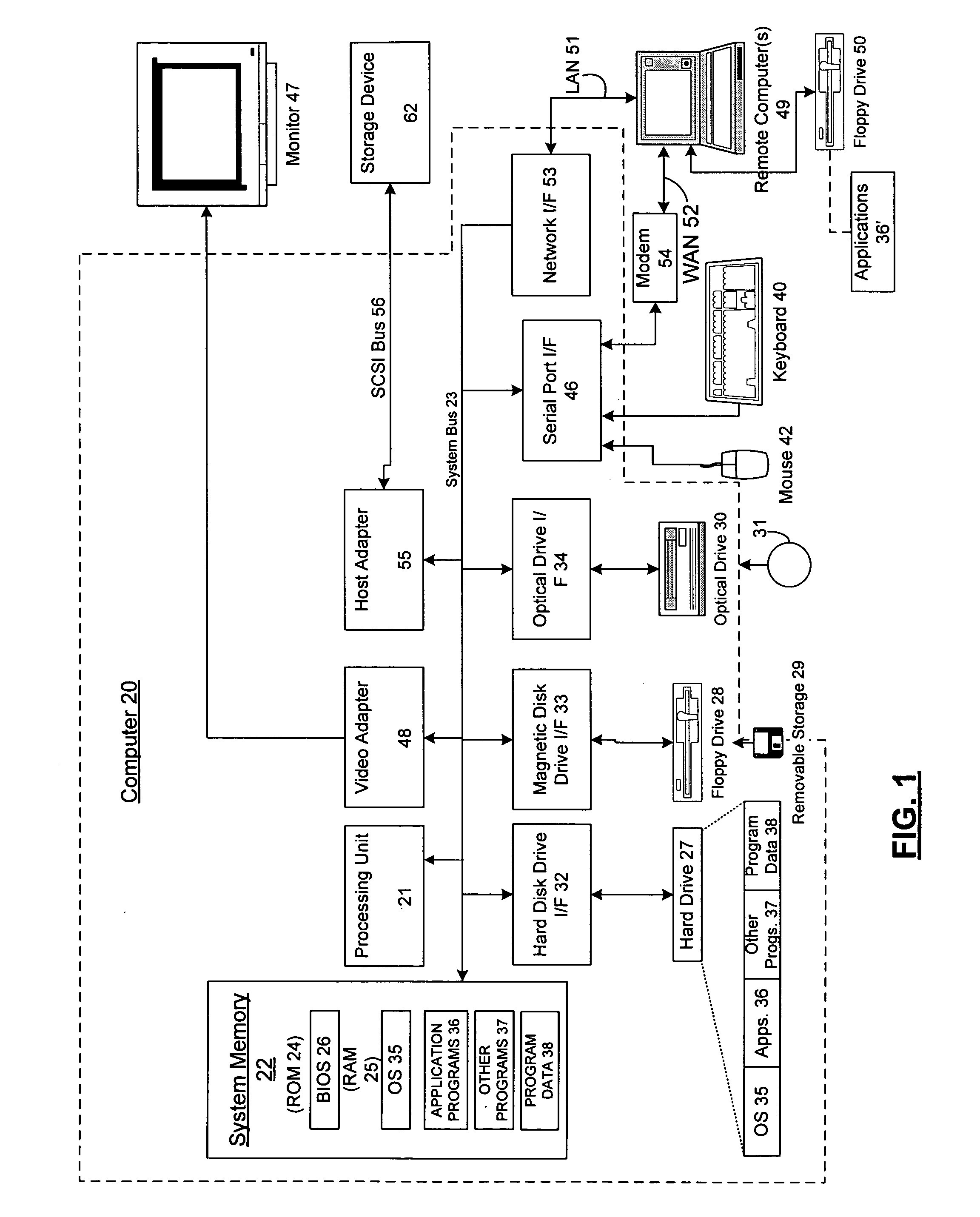
[0027] Numerous embodiments of the present invention may execute on a computer. FIG. 1 and the following discussion is intended to provide a brief general description of a suitable computing environment in which the inv...


PUM


Abstract

The present invention is directed to systems and methods for providing disaster recovery services using virtual machines. The invention provides an inexpensive and minimally intrusive way to provide disaster recovery services including recovery of the state of computer processors and devices. The system includes a production host and a backup host that communicate via a communications link. The state of the processor and devices on the production host are periodically stored onto backup host and can be restored in the event of an emergency. Additionally, the invention includes two business methods for utilizing the system and methods for providing disaster recovery services.

Description

CROSS-REFERENCE TO RELATED APPLICATIONS [0001] This application is related to the following commonly-assigned patent applications, the entire contents of each are hereby incorporated herein this present application by reference: U.S. patent application Ser. No. 10 / 193,531, entitled “METHOD FOR FORKING OR MIGRATING A VIRTUAL MACHINE”, filed July 11, 2002 (Atty. Docket No. MSFT-2562 / 304106.01).FIELD OF THE INVENTION [0002] The present invention generally relates to the field of virtual machines (also known as “processor virtualization”) and software that executes in a virtual machine environment, as well as to information technology (IT) disaster recovery services. More specifically, the present invention is directed to a low-cost and minimally-disruptive disaster recovery system utilizing virtual machine software running on at least two host computers in physically different locations, as well as to methods for using same, for restoring the state of a virtual machine in the event of ...

Claims


Application Information

Patent Timeline
Patent Type & Authority Applications(United States)
IPC IPC(8): G06F9/46
CPCG06F11/1438G06F11/2025G06F11/2038G06F11/2097
Inventor TRAUT, ERIC P.
Owner MICROSOFT TECH LICENSING LLC
Why Eureka
Try Eureka