Sandwiched thermal solution

a technology of thermal solution and sandwiched shell, which is applied in the direction of lighting and heating apparatus, instruments, and semiconductor/solid-state device details, etc., can solve the problems of system failure, degrade the performance and reliability of the overall system, and harm the own performance, so as to improve mechanical robustness and handleability of thermal solution, high thermal anisotropic ratio, and improve the effect of mechanical robustness and handleability

Active Publication Date: 2006-04-27
NEOGRAF SOLUTIONS LLC
View PDF21 Cites 41 Cited by
  • Summary
  • Abstract
  • Description
  • Claims
  • Application Information

AI Technical Summary

Benefits of technology

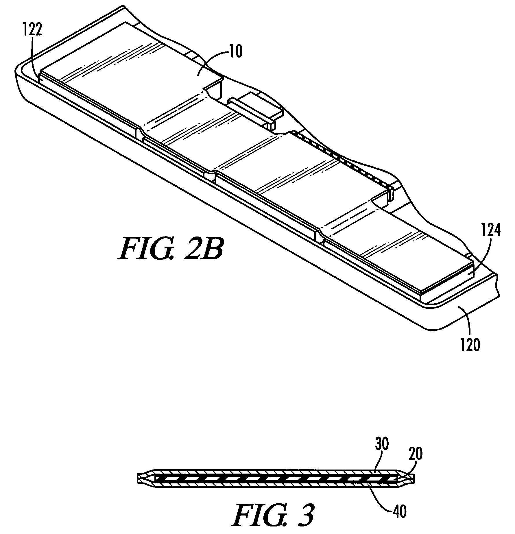
[0028] In addition, in order to improve mechanical robustness and handleability of the thermal solution, and potentially to further block or shield heat from being transmitted from the heat source to the external surface of the device or to other device components, a layer of a relatively thermally non-conductive material such as a plastic like Mylar® material or other resins or like materials can be overlaid on the thermal solution.
[0029] Accordingly, it is an object of the present invention to provide an improved thermal solution for simultaneously dissipating the heat from a component of an electronic device and shielding adjacent structures from the heat.
[0030] Still another object of the present invention is the provision of a thermal solution having a sufficiently high thermal anisotropic ratio to function effectively for heat dissipation while avoiding heat transfer to adjacent structures.

Problems solved by technology

However, microprocessors, integrated circuits and other sophisticated electronic components typically operate efficiently only under a certain range of threshold temperatures.
The excessive heat generated during operation of these components can not only harm their own performance, but can also degrade the performance and reliability of the overall system and can even cause system failure.
The increasingly wide range of environmental conditions, including temperature extremes, in which electronic systems are expected to operate, exacerbates the negative effects of excessive heat.
As such, external surfaces of the device can become heated, which can be uncomfortable or even dangerous to the user.
Moreover, the heat generated by one component in a device can adversely affect an adjacent component.
Although one potential solution is to insulate the heat source, this is not a satisfactory solution, since doing so keeps the heat generated by the heat source concentrated at the heat source, potentially damaging the heat source.
In thinner laptops, the heat generated by the hard drive can be transferred through the laptop case to the user's palm, causing discomfort and even pain.
Indeed, in some laptops, the palm rest temperature has been measured to be higher than 40° C. Likewise, heat-generating components can cause the bottom of a laptop computer to become heated, causing discomfort or even pain to the user when the laptop is positioned in the user's lap.
This has become a significant problem for makers of laptop computers, and other portable devices where there is a continuing effort to make the devices smaller for greater portability.
While the use of sheets of compressed particles of exfoliated graphite (i.e., flexible graphite) has been suggested as thermal spreaders, thermal interfaces and as component parts of heat sinks for dissipating the heat generated by a heat source (see, for instance, U.S. Pat. Nos. 6,245,400; 6,482,520; 6,503,626; and 6,538,892), the issues of “touch temperature,” that is the heating of external surfaces of an electronic device to the extent that the user is discomfited or endangered, and heating of adjacent components have not adequately been addressed.
Moreover, the flexible nature of graphite materials makes it difficult to form complex structures or shapes with the graphite materials.
In addition, the attachment of graphite fins to metallic bases is also problematic, since graphite cannot be soldered into place in the same way metallic fins can.
Another issue with the use of graphite in electronic components is the fear, which may be unfounded, that individual graphite particles or flakes may flake off a graphite heat dissipation component.
Given the electrical conductivity of graphite, this would have the potential to interfere with the operation of the component in which the graphite material is located.

Method used


Image

  • Sandwiched thermal solution
  • Sandwiched thermal solution
  • Sandwiched thermal solution

Examples


example i

[0099] The thermal characteristics of the several embodiments of the inventive sandwich were compared with those of several materials often employed as thermal solutions for electronic equipment, by measuring thermal conductivity (Tc), expressed as W / m° K, and thermal diffusivity (Td), expressed as mm2 / sec. Each of the samples tested were 1.3 mm in total thickness, and comprised: [0100] (1) flexible graphite; [0101] (2) copper; [0102] (3) aluminum; [0103] (4) aluminum nitride; [0104] (5) a sandwich formed of 0.5 mm copper, 1.2 mm of the flexible graphite of material (1), and 0.5 mm of copper; [0105] (6) a sandwich formed of 0.5 mm aluminum, 1.2 mm of the flexible graphite of material (1), and 0.5 mm of aluminum; and [0106] (7) a sandwich formed of 0.5 mm aluminum nitride, 1.2 mm of the flexible graphite of material (1), and 0.5 mm of aluminum nitride.

[0107] The results are set out in Table I:

TABLE IThermalSampleconductionThermal diffusionGraphite240230Cu368108Al21098Aluminum nitr...

example ii

[0108] The thermal characteristics of different embodiments of the inventive sandwich were compared with those of several materials often employed as thermal solutions for electronic equipment, by measuring thermal conductivity (Tc), expressed as W / m° K, and thermal diffusivity (Td), expressed as mm2 / sec. Each of the samples tested were 1.5 mm in total thickness, and comprised: [0109] (1) aluminum; [0110] (2) silicon; [0111] (3) flexible graphite; [0112] (4) a sandwich formed of 0.1 mm aluminum, 1.3 mm of silicon, and 0.1 mm of aluminum; [0113] (5) a sandwich formed of 0.1 mm silicon, 1.3 mm of aluminum, and 0.1 mm of silicon; [0114] (6) a sandwich formed of 0.1 mm aluminum, 1.3 mm of the flexible graphite of material (3), and 0.1 mm of aluminum; and [0115] (7) a sandwich formed of 0.1 mm of the flexible graphite of material (3), 1.3 mm of aluminum, and 0.1 mm of the flexible graphite of material (3).

[0116] The results are set out in Table II:

TABLE IIThermalThermalSampleconductio...

example iii

[0117] A series of sandwich thermal solutions was prepared, using graphite materials having different thermal conductivities. In each case, the sandwich was 1.55 mm in thickness, 15 mm in width and 400 mm in length. The sandwiches were subject to 200 tons of pressure to eliminate air between the layers. A 10 watt heat source was placed 20 mm in from one of the edges of the sandwich, a first thermocouple was placed 20 mm in from an edge of the sandwich opposite the heat source, and a second thermocouple was placed 200 mm from the first thermocouple. The thermal conductivity and thermal diffusivity of each sample was then calculated. The samples tested were: [0118] (1) a sandwich formed of 0.05 mm aluminum, 1.45 mm of graphite having a thermal conductivity of 200 W / m° K, and 0.05 mm of aluminum; [0119] (2) a sandwich formed of 0.05 mm aluminum, 1.45 mm of graphite having a thermal conductivity of 400 W / m° K, and 0.05 mm of aluminum; [0120] (3) a sandwich formed of 0.05 mm aluminum, 1....


PUM


Abstract

A thermal solution for an electronic device, which is positioned between a heat source and an external surface of the electronic device and/or another component of the electronic device, where the thermal solution facilitates heat dissipation from the heat source while shielding the external surface and/or second component from the heat generated by the heat source.

Description

TECHNICAL FIELD [0001] The present invention relates to a thermal solution capable of managing the heat from a heat source such as a component of an electronic device, so as to dissipate heat generated by the heat source while mediating the effects of the heat on users of the device and other device components. BACKGROUND OF THE INVENTION [0002] With the development of more and more sophisticated electronic devices, including those capable of increasing processing speeds and higher frequencies, having smaller size and more complicated power requirements, and exhibiting other technological advances, such as microprocessors and integrated circuits in electronic and electrical components, high capacity and response memory components such as hard drives, electromagnetic sources such as light bulbs in digital projectors, as well as in other devices such as high power optical devices, relatively extreme temperatures can be generated. However, microprocessors, integrated circuits and other...

Claims


Application Information

Patent Timeline
Patent Type & Authority Applications(United States)
IPC IPC(8): F28F7/00
CPCG06F1/203H01L23/373Y10T428/30H01L2924/0002H01L2924/00
Inventor FUJIWARA, KIKUOTOZAWA, MASAAKISHIVES, GARY D.NORLEY, JULIANREYNOLDS, ROBERT ANDERSON III
Owner NEOGRAF SOLUTIONS LLC
Why Eureka
Try Eureka