Active matrix type liquid crystal display apparatus

Inactive Publication Date: 2006-04-27
PANASONIC LIQUID CRYSTAL DISPLAY CO LTD +1
View PDF21 Cites 12 Cited by
  • Summary
  • Abstract
  • Description
  • Claims
  • Application Information

AI Technical Summary

Benefits of technology

[0056] In a liquid crystal in which the anisotropy Δn of the refractive index is relatively small, the change in the anisotropy Δn itself of its refractive index becomes small. In addition, if the thickness deff is also small, the change in the

Problems solved by technology

However, in a display system of this type wherein the direction of an electric field applied to the liquid crystal is controlled to be parallel with the surface of a substrate by using active elements (hereinafter referred to as a horizontal electric field type), no consideration is given to the characteristic of the light source required to decrease the power consumption of the whole liquid crystal display apparatus.
Further, no consideration is given to the configuration of the liquid crystal display apparatus required to suppress color shift in response to the application of a voltage thereto and to prevent a color defect from occurring.
Because the luminous efficiency of the fluorescent lamp in a s

Method used


Image

  • Active matrix type liquid crystal display apparatus
  • Active matrix type liquid crystal display apparatus
  • Active matrix type liquid crystal display apparatus

Examples


embodiment a

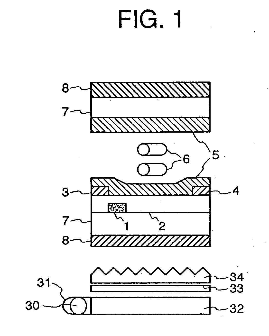
[0150] The liquid crystal display apparatus has two substrates, one of which has a color filter with B, G and R pixels on its surface. A nemnatic liquid crystal composition is inserted between the substrates, of which the anisotropy of the dielectric constant is positive, +12.0, and the anistropy of the refractive index is 0.079 (589 nm, 20° C.). The gap d between cells is formed by scattering spherical polymer beads and sandwiching them between the substrates. The gap is adjusted to d=2.87 μm by selecting the radius of the beads.

[0151] In this comparison example, dLC·Δn (589 nm) equals 0.227 μm and dLC·Δn (490 nm) equals 0.232 μm. As a result, deff·Δn (490 nm) equals about 0.21 μm. This value is out of the present invention.

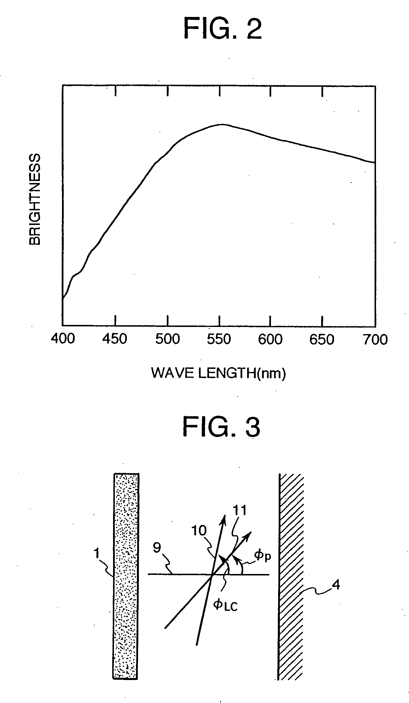
[0152] The liquid crystal display panel is provided with a back-light unit as a light source which has a color temperature of 6818K.

embodiment b

[0153] The liquid crystal display apparatus has two substrates, one of which has a color filter with B, G and R pixels on its surface. A nematic liquid crystal composition is inserted between the substrates, of which the anisotropy of the dielectric constant is positive, +12.0, and the anisotropy of the refractive index is 0.079 (589 nm, 20° C.). The gap d between cells is formed by scattering spherical polymer beads and sandwiching them between the substrates. The gap is adjusted to d=3.17 μm by selecting a radius of the beads which is different from that in embodiment A.

[0154] In this embodiment B, dLC·Δn (589 nm) equals 0.250 μm and dLC·Δn (490 nm) equals 0.256 μm. As a result, deff Δn (490 nm) equals about 0.23 μm.

[0155] The liquid crystal display panel is provided with a back-light unit as a light source which has a color temperature of 4703K.


PUM


Abstract

A liquid crystal display apparatus includes a liquid crystal panel including a pair of polarizers, and a back light provided at a back side of said liquid crystal panel. The liquid crystal panel is an active matrix type liquid crystal panel enabling display and has a characteristic of spectral transmittance required to satisfy the following equation, x>y, when a drive voltage is applied thereto so as to vary from a dark state to a light state, in which “x” is a value of the transmittance in the liquid crystal panel at a wavelength which corresponds to one of 490 nm and 500 nm, and “y” is a value of the transmittance in the liquid crystal panel at a wavelength which corresponds to 545 nm.

Description

CROSS REFERENCE TO RELATED APPLICATION [0001] This is a continuation of U.S. application Ser. No.10 / 629,711, filed Jul. 30, 2003, which is a continuation of U.S. application Ser. No. 09 / 572,375, filed May 18, 2000, now U.S. Pat. No. 6,621,538, which is a continuation of U.S. application Ser. No. 08 / 740,008, filed Oct. 23, 1996, now U.S. Pat. No. 6,137,560, the subject matter of which is incorporated by reference herein.BACKGROUND OF THE INVENTION [0002] The present invention relates to a liquid crystal display apparatus, and, more particularly, to an active matrix liquid crystal display apparatus. [0003] Various examples of liquid crystal display apparatus are disclosed, for example, in Japanese Patent Publication No. 63-21907 (1988), UP, W091 / 10936 and Japanese Patent Application Laid-Open No. 6-222397 (1994), in which a pair of comb electrodes are used to apply an electric field to a liquid crystal in a direction parallel to the surface of a substrate. However, in a display system...

Claims


Application Information

Patent Timeline
IPC IPC(8): G09G3/36G02F1/13357G02F1/1343
CPCG02F1/133371G02F1/133512G02F1/133514G02F1/133604G02F1/133609G02F1/134363G09G3/3406G09G3/3648G09G2300/0434G09G2320/0242G09G2330/021G02F1/1343G02F1/136
Inventor UTSUMI, YUKAKONDO, KATSUMIHIYAMA, IKUOITOH, OSAMUOHE, MASAHITOYANAGAWA, KAZUHIKOASHIZAWA, KEIICHIRO
Owner PANASONIC LIQUID CRYSTAL DISPLAY CO LTD
Why Eureka
Try Eureka