Multicarrier receiver and transmitter with delay correcting function

a receiver and delay correction technology, applied in multi-frequency code systems, phase-modulated carrier systems, baseband system details, etc., can solve problems such as difficulty in analysing power amplifier distortion, and achieve the effect of not increasing the configuration of each analog section in cost and siz

Inactive Publication Date: 2006-04-27
KOKUSA ELECTRIC CO LTD
View PDF2 Cites 33 Cited by
  • Summary
  • Abstract
  • Description
  • Claims
  • Application Information

AI Technical Summary

Benefits of technology

[0026] The present invention has been made in view of the above background. An object of the present invention is to provide a multicarrier receiver which suppresses a delay time deviation in a receiving section for each carrier without increasing the configuration of each analog section in cost and size.
[0035] According to the multicarrier receiver according to the present invention, the accuracy of a request for a delay deviation with respect to each analog part can be reduced. It is therefore possible to bring the analog part into less cost and size.
[0036] According to the transmitter according to the present invention, the use of a delay detector and a delay corrector makes it possible to perform matching in timing between each of transmit signals and each of feedback signals originally shifted in timing, with a high degree of precision. A distortion compensation algorithm for performing comparisons every samples between the transmit signals and the feedback signals.

Problems solved by technology

It is thus difficult to analyze the distortion of the power amplifier 1004.

Method used


Image

  • Multicarrier receiver and transmitter with delay correcting function
  • Multicarrier receiver and transmitter with delay correcting function
  • Multicarrier receiver and transmitter with delay correcting function

Examples


first preferred embodiment

[0057]FIG. 1 is a configuration diagram showing an essential part of a first embodiment of a multicarrier receiver according to the present invention and shows only constituent portions different from FIG. 16 and their peripheries. Reference numeral 201 indicates an F-LPF (Fractional Low Pass Filter). Constituent portions corresponding to those shown in FIG. 16 are given the same reference numerals respectively, and dual explanations thereof are omitted.

[0058] In the same drawing, the first embodiment includes the F-LPF 201 provided in a stage subsequent to an LPF 108 under the configuration shown in FIG. 16. Incidentally, it is also possible to combine the LPF 108 and the F-LPF 201 together and allow the LPF 108 to share the role of the F-LPF 201. However, these functions are illustrated in parts to make easy understanding. Any of HPF, LPF and BPF may be adopted as the F-LPF 201 if their functions are satisfied.

second preferred embodiment

[0059]FIG. 2 is a configuration diagram showing an essential part of a second embodiment of a multicarrier receiver according to the present invention and illustrates only constituent portions different from FIG. 16 and their peripheries. Reference numeral 202 indicates an F-BPF (Fractional Band Pass Filter). Constituent portions corresponding to those shown in FIG. 16 are given the same reference numerals respectively, and dual explanations thereof are omitted.

[0060] In the same drawing, the second embodiment includes the F-BPF 202 provided between an A / D converter 106 and a quadrature detector 107 under the configuration shown in FIG. 16. Incidentally, any of HPF, LPF and BPF may be used as the F-BPF 202 if their functions are satisfied.

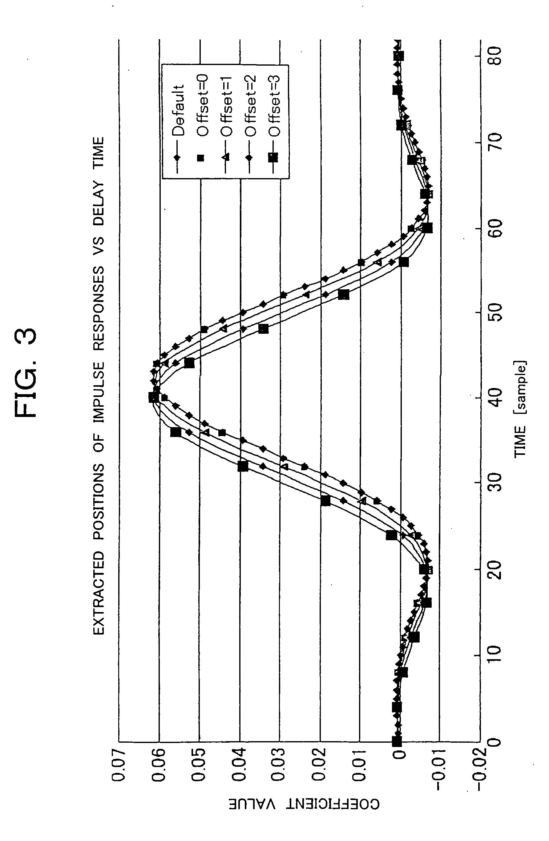
[0061] The principle of delay correction by filters will be explained below using FIG. 3.

[0062]FIG. 3 shows impulse responses designed for a given LPF, which are extracted every 4 samples from positions where they are shifted by 0 to 4 samples. ...

third preferred embodiment

[0064]FIG. 4 is a configuration diagram showing an essential part of a third embodiment of a multicarrier receiver according to the present invention, which is suitable for use in an RRU (Remote Radio Unit, which is also called forward base station or extension base station) in a CDMA cellular phone infrastructure. Reference numerals 401 and 402 are shift registers respectively. Constituent portions corresponding to those shown in FIGS. 16 and 1 are given the same reference numerals respectively.

[0065] In the same drawing, the third embodiment includes the shift register 401 provided between the A / D converter 106 and the quadrature detector 107, and the shift register 402 provided between the LPF 108 and F-LPF 201 for 1 and Q phases under the configurations shown in FIGS. 16 and 1. Incidentally, a section prior to the A / D converter 106 is identical to the configuration shown in FIG. 16. Thus, the third embodiment is different from the first embodiment in that the shift registers 40...


PUM


Abstract

A multicarrier receiver that receives N carrier frequencies therein comprises N A / D converters each of which analog-digital converts a receive signal at a sample rate fs for each carrier, N quadrature detectors which receive outputs sent from the N A / D converters therein and digitally quadrature-detect the outputs, respectively, 2N LPFs which allow only desire bands of outputs of the N quadrature detectors to pass therethrough, and N delay time correcting means each of which corrects a processing delay time deviation for each carrier inside the multicarrier receiver in a time unit of less than 1 / fs using a fractional delay filter. The delay time correcting means has, for example, an M-stage shift register which operates at fs and generates a delay of M / fs, and a fractional delay filter which operates at fs and includes an even number of tap coefficients and which generates a delay different from M / fs by 0.5 / fs.

Description

BACKGROUND OF THE INVENTION [0001] 1. Field of the Invention [0002] The present invention relates to a multicarrier receiver and a transmitter with a delay correcting function, and particularly to a multicarrier receiver which suppresses a deviation in delay time for each carrier at a receiving section upon dealing with a multicarrier, and a transmitter with a delay correcting function which corrects a delay between transmission and feedback for a distortion analysis. [0003] 2. Description of the Related Art [0004]FIG. 15 is a configuration diagram showing one example of a conventional multicarrier receiver. [0005] In the same drawing, reference numeral 101 indicates a DUPlexer (DUP) which has a filter whose one end is connected to an antenna (not shown) capable of transmitting and receiving a multicarrier and which separates a transmit signal to the antenna and a receive signal from the antenna, using the difference between frequencies for transmission and reception. [0006] Referen...

Claims


Application Information

Patent Timeline
Patent Type & Authority Applications(United States)
IPC IPC(8): H04L25/49H04L27/22
CPCH04L5/06H04L27/2626H04L27/2637H04L27/2662H04L27/266
Inventor MIYATANI, TETSUHIKOOKADA, TAKASHI
Owner KOKUSA ELECTRIC CO LTD
Why Eureka
Try Eureka