Die cushion mechanism, and apparatus and method for controlling the same

Active Publication Date: 2006-05-04
FANUC LTD
View PDF11 Cites 21 Cited by
  • Summary
  • Abstract
  • Description
  • Claims
  • Application Information

AI Technical Summary

Benefits of technology

[0009] It is an object of the present invention to provide a control apparatus for a die cushion mechanism including a servo-motor as a drive source and producing a force adapted to be applied to a slide in a press machine, which

Problems solved by technology

However, as a conventional die cushion mechanism uses a hydraulic or pneumatic device as the drive source, it has generally been difficult to control the force (or pressure) applied to the slide so as to correspond to a command value in a variable mode, in response to a sudden pressure variation due to external causes, such as the collision with the slide, etc.
However, it is difficult, with only such a simple change of the control scheme, to properly control the force (or pressure) of the cushion pad quickly in response to a significant pressure fluctuation due to the impact of collision.
However, the response of an integrator is generally not fast enough, and there may be a case that it is difficult to hold a proper speed command following a rapid fluctuation of the force at the time of collision.
In th

Method used


Image

  • Die cushion mechanism, and apparatus and method for controlling the same
  • Die cushion mechanism, and apparatus and method for controlling the same
  • Die cushion mechanism, and apparatus and method for controlling the same

Examples


first embodiment

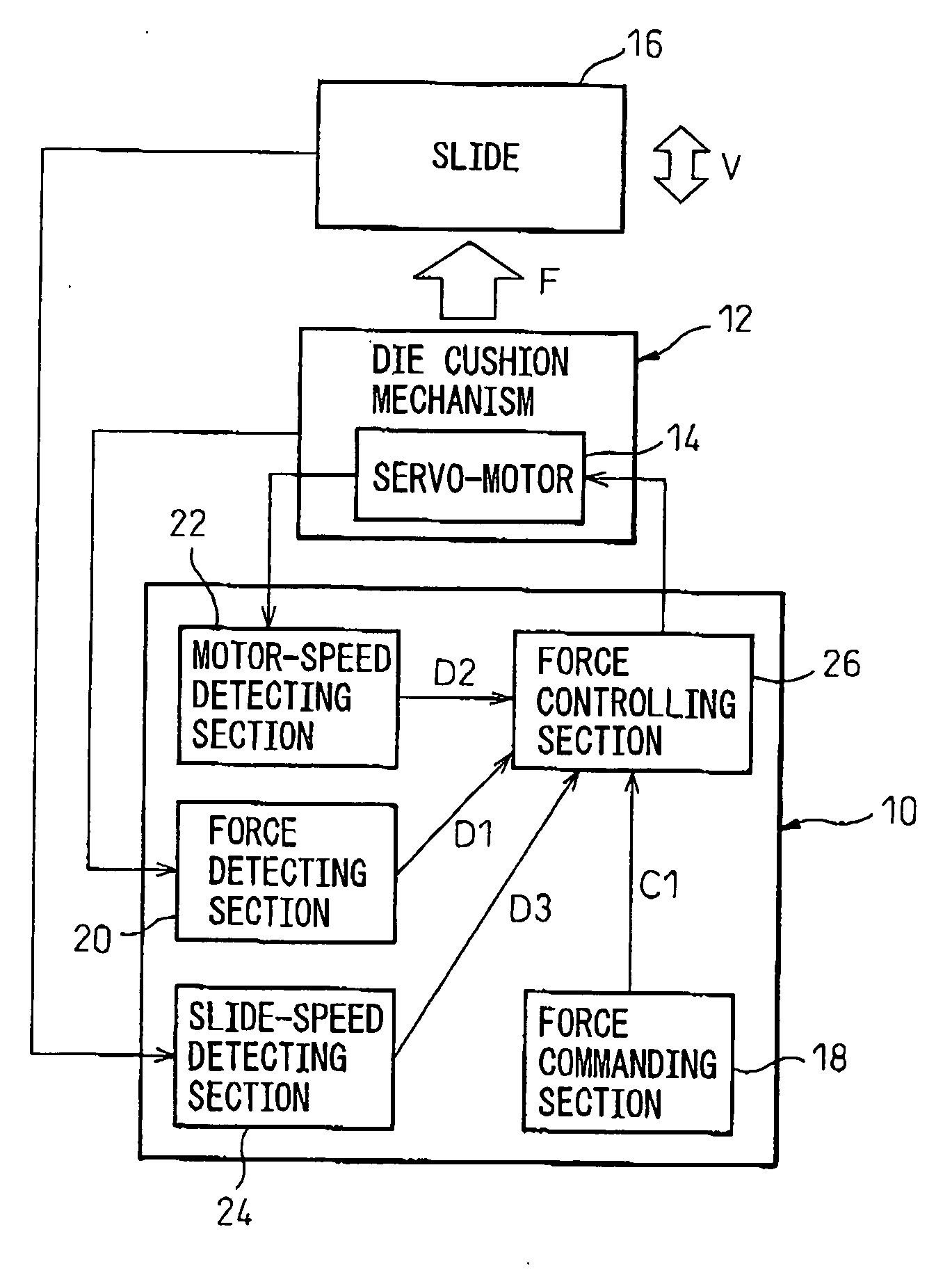
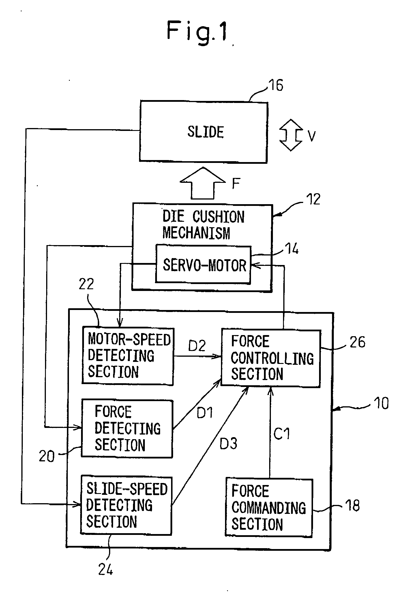
[0033] In a control apparatus 10 shown in FIG. 3, the force controlling section 26 includes a speed calculating section 34 for calculating, from the force command value C1 and the force detected value D1, a speed command value C2 to be commanded to the servo-motor 14; and a speed controlling section 36 for correcting the speed command value C2 calculated by the speed calculating section 34 by using the slide-speed detected value D3, and controlling the operating speed R of the servo-motor 14 based on the corrected speed command value and the motor-speed detected value D2 (i.e., subtracting the operating speed feedback value of the servo-motor 14 from the speed command value after being corrected). Thus, the force controlling section 26 executes the force control by controlling the operating speed R of the servo-motor 14. In this connection, it is advantageous that the speed controlling section 36 corrects the speed command value C2 by adding the slide-speed detected value D3 to the...

second embodiment

[0035] In the control apparatus 10 shown in FIG. 4, the force commanding section 18 includes a time-constant setting section 38 for setting a rise time constant T of the force command value C1. Also, the force controlling section 26 includes a time-constant adjusting section 40 for adjusting the rise time constant T set by the time-constant setting section, on the basis of the slide-speed detected value D3 detected by the slide-speed detecting section 34. Thus, the force controlling section 26 executes the force control on the basis of the force command value C1 including the rise time constant T adjusted by the time-constant adjusting section 40.

[0036] If the force control is not based on a step-like force command but is based on the force command value C1 including the desired rise time constant T, the force deviation at the initial stage of control is diminished, so that the overshoot of the force can be effectively reduced. Further, in the above configuration, the rise time con...

third embodiment

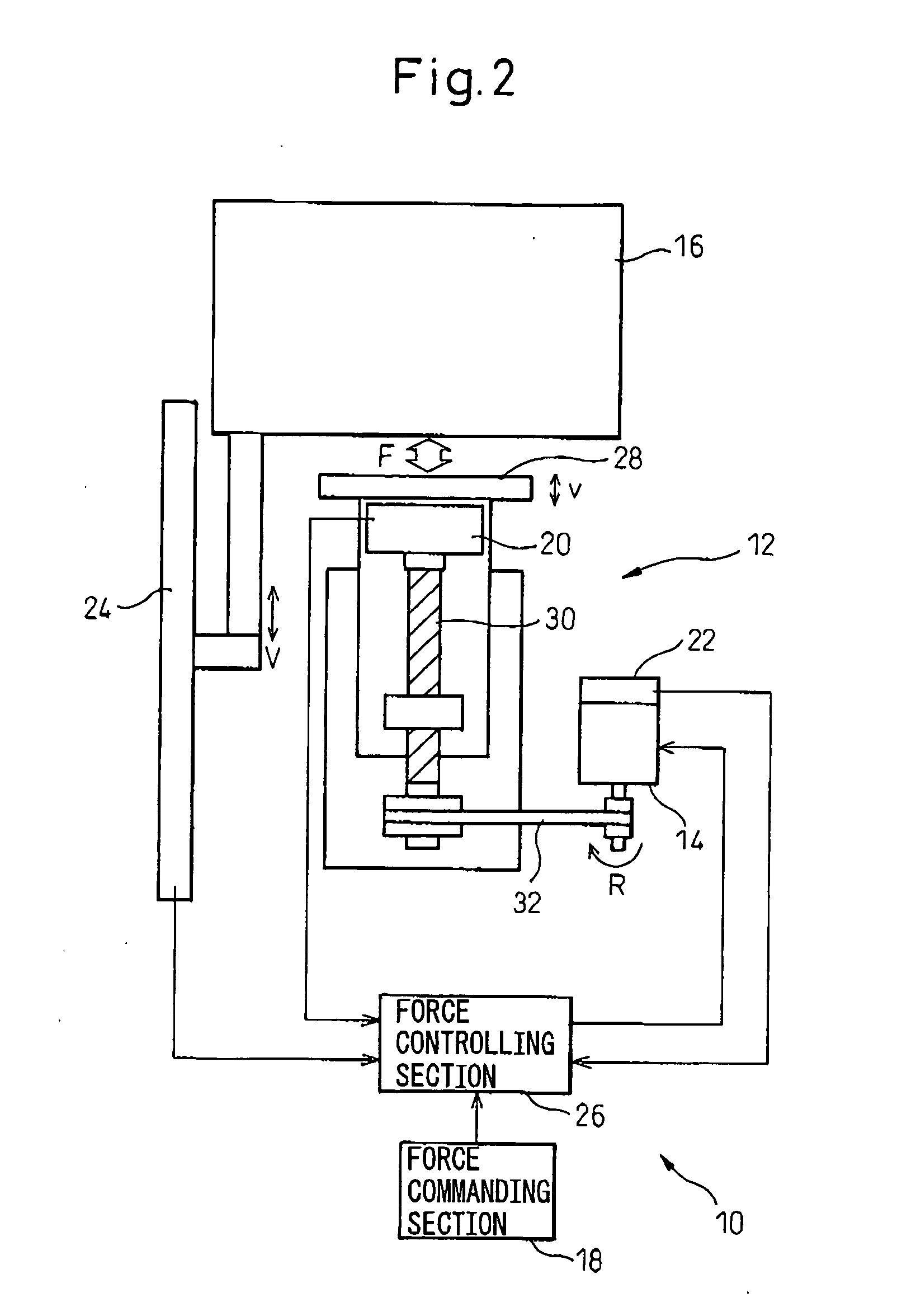
[0040] The control apparatus 10 shown in FIG. 6 is particularly effective in the configuration wherein the cushion pad 28 is operated in a preliminary acceleration motion just before collision. In this embodiment, the control apparatus 10 further includes a speed commanding section 44 for commanding a preliminary-speed command value C3 used for the above-described preliminary acceleration control to the speed controlling section 42 of the force controlling section 26. The speed controlling section 42 adjusts the preliminary-speed command value C3 commanded by the speed commanding section 44 on the basis of the slide-speed detected value D3 detected by the slide-speed detecting section 24. Thereby, when the cushion pad 28 is moved in the preliminary acceleration, it is possible to start the servo-motor 14 at an optimum preliminary speed v corresponding to the actual moving speed V of the slide 16.

[0041] In the third embodiment described above, it is advantageous that the speed contr...


PUM

PropertyMeasurementUnit
Timeaaaaaaaaaa
Forceaaaaaaaaaa
Pressureaaaaaaaaaa

Abstract

A control apparatus for controlling a die cushion mechanism including a servo-motor as a drive source and producing a force adapted to be applied to a slide in a press machine. The control apparatus includes a force commanding section for commanding a force to be produced by the die cushion mechanism; a force detecting section for detecting the force produced by the die cushion mechanism; a motor-speed detecting section for detecting an operating speed of the servo-motor; a slide-speed detecting section for detecting a moving speed of the slide; and a force controlling section for executing a force control on the servo-motor, based on a force command value commanded by the force commanding section, a force detected value detected by the force detecting section, a motor-speed detected value detected by the motor-speed detecting section and a slide-speed detected value detected by the slide-speed detecting section.

Description

BACKGROUND OF THE INVENTION [0001] 1. Field of the Invention [0002] The present invention relates to a die cushion mechanism, and also to an apparatus and a method for controlling the die cushion mechanism. [0003] 2. Description of the Related Art [0004] In a press machine for performing press working, such as bending, drawing, stamping, etc., it is known that a die cushion mechanism is provided as an auxiliary apparatus for applying, during a pressing operation, a required force (or pressure) to a movable support member (generally referred to as a slide) supporting a first die used for the press working, from the side of a second support member (generally referred to as a bolster) supporting a second die. The die cushion mechanism is usually constructed such that a movable element (generally referred to as a cushion pad) retained under a predetermined pressure is arranged to collide directly or indirectly with the slide (or the first die) moving in a die-closing direction and, afte...

Claims


Application Information

Patent Timeline
IPC IPC(8): B30B15/26
CPCB21D24/02G05B19/19G05B2219/41139G05B2219/42087G05B2219/45131
Inventor IWASHITA, YASUSUKEOKITA, TADASHIKAWAMURA, HIROYUKIIKAI, SATOSHI
Owner FANUC LTD
Why Eureka
Try Eureka