Control apparatus for internal combustion engine

a control apparatus and internal combustion engine technology, applied in the direction of electric control, combustion-air/fuel-air treatment, machines/engines, etc., can solve the problems of insufficient torque and lean air-fuel ratio in fail-safe mode, and achieve the suppression of combustion variation, increase the purge rate, and reduce the overlap of intake valves and exhaust valves

Inactive Publication Date: 2006-05-04
TOYOTA JIDOSHA KK
View PDF3 Cites 94 Cited by
  • Summary
  • Abstract
  • Description
  • Claims
  • Application Information

AI Technical Summary

Benefits of technology

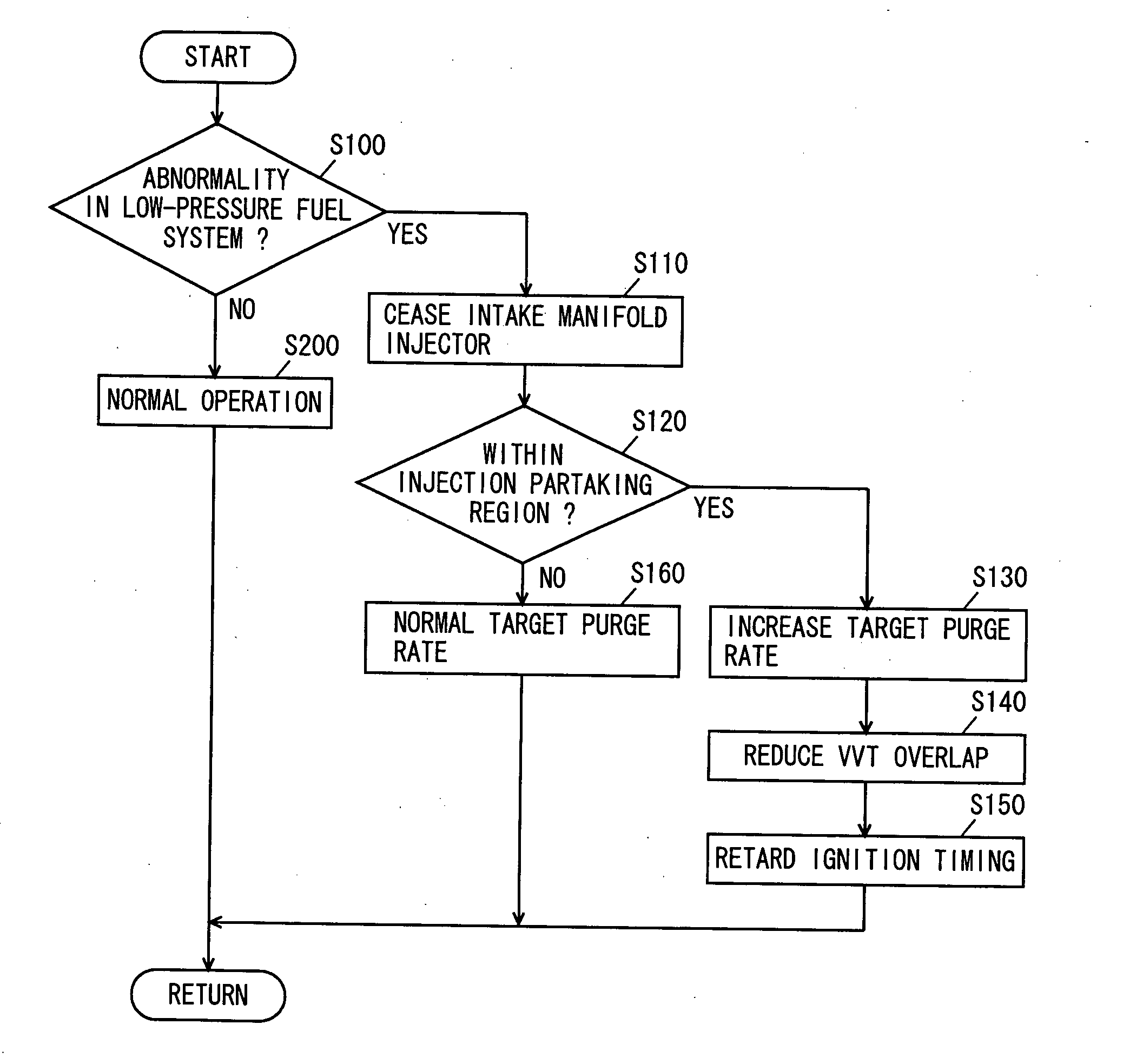
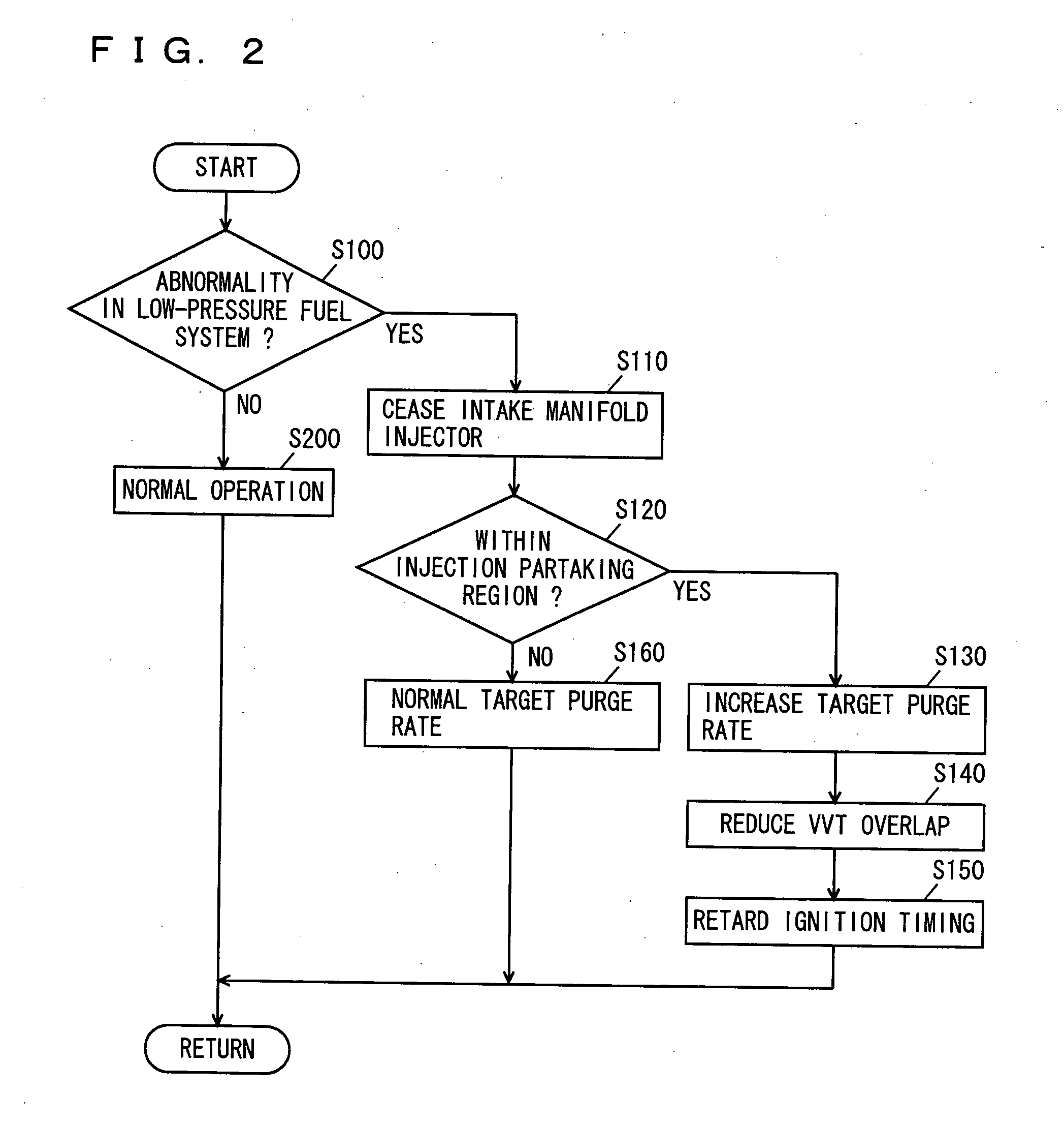
[0015] In accordance with the present invention, reduction in the fuel quantity from the intake manifold injector in which abnormality is sensed is compensated for from the intake system apparently by increasing the purge rate. Accordingly, fuel can be compensated for from the intake system with a favorable mixing state of the intake air and fuel. Therefore, combustion variation can be suppressed in the case where fuel cannot be injected from the intake manifold injector.
[0016] Further preferably, the control apparatus further includes an adjustment unit adjusting a variable valve timing mechanism provided at the internal combustion engine such that overlap of intake valves and exhaust valves is reduced when fuel injection is not conducted from the second fuel injection mechanism as a result of determination of abnormality in the second fuel supply system by the abnormality determination unit as compared to a case where determination is not made of abnormality in the second fuel supply system.
[0017] In accordance with the present invention, the overlap of the intake valves and exhaust valves can be reduced to suppress intake blow-back from the combustion chamber. Accordingly, accumulation of deposits at the intake manifold injector or intake port caused by the PM (Particulate Matters) included in the blow-back can be suppressed. Since the state of no accumulation of deposits can be maintained when fuel injection from the intake manifold injector is not conducted as long as the intake manifold injector itself is absent of failure, that intake manifold injector can be .used even after, for example, repair of the harness. Further, since the combustion state is improved due to reduction in the internal EGR (Exhaust Gas Recirculation) factor when the overlap of the intake valves and exhaust valves is reduced, torque variation can be suppressed.

Problems solved by technology

However, since the intake manifold injector is set to take an auxiliary role of the in-cylinder injector, fuel of a quantity corresponding to the intake air at the time of full opening of the throttle valve cannot be supplied, whereby the air-fuel ratio in the fail-safe mode will become lean.
There may be the case where the torque is insufficient due to combustion defect.
However, this publication is silent about failure in the intake manifold injector and in the fuel supply system that supplies fuel to the intake manifold injector.

Method used


Image

  • Control apparatus for internal combustion engine
  • Control apparatus for internal combustion engine
  • Control apparatus for internal combustion engine

Examples


Embodiment Construction

[0035] Embodiments of the present invention will be described hereinafter with reference to the drawings. The same components have the same reference characters allotted, and their designation and function are also identical. Therefore, detailed description thereof will not be repeated.

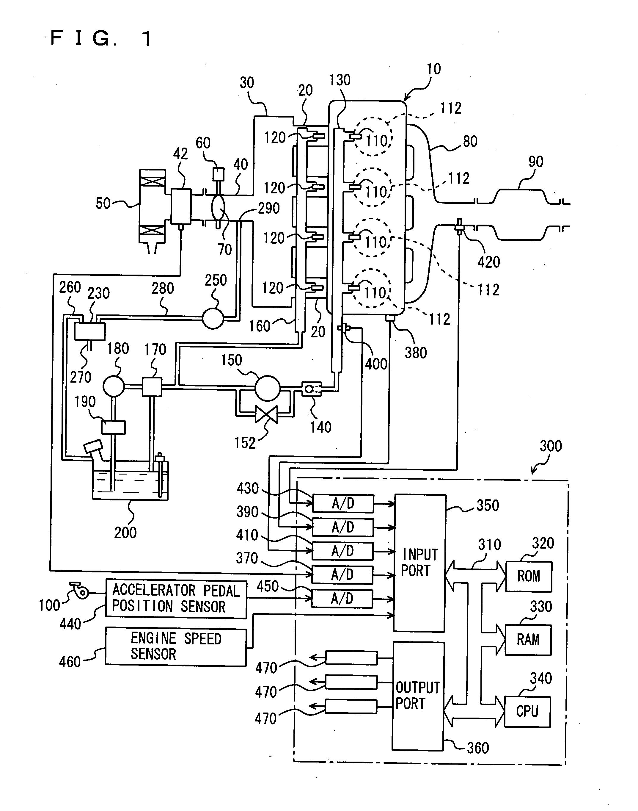
[0036]FIG. 1 is a schematic view of a structure of an engine system under control of an engine ECU (Electronic Control Unit) identified as a control apparatus for an internal combustion engine according to an embodiment of the present invention. Although an in-line 4-cylinder gasoline engine is indicated as the engine, the present invention is not limited to such an engine.

[0037] As shown in FIG. 1, the engine 10 includes four cylinders 112, each connected to a common surge tank 30 via a corresponding intake manifold 20. Surge tank 30 is connected via an intake duct 40 to an air cleaner 50. An airflow meter 42 is arranged in intake duct 40, and a throttle valve 70 driven by an electric motor 60 is a...


PUM


Abstract

An engine ECU executes a program including the steps of: determining presence of abnormality in a low-pressure fuel system; ceasing an intake manifold injector when determination is made of abnormality in the low-pressure fuel system; increasing the target purge rate when the engine operation state attains an injection partaking state between an in-cylinder injector and an intake manifold injector; reducing the VVT overlap; and retarding the ignition timing.

Description

[0001] This nonprovisional application is based on Japanese Patent Application No. 2004-319116 filed with the Japan Patent Office on Nov. 2, 2004, the entire contents of which are hereby incorporated by reference. BACKGROUND OF THE INVENTION [0002] 1. Field of the Invention [0003] The present invention relates to an internal combustion engine including a first fuel injection mechanism (in-cylinder injector) for injecting fuel into a cylinder and a second fuel injection mechanism (intake manifold injector) for injecting fuel towards an intake manifold or intake port. Particularly, the present invention relates to the technique of suppressing torque variation in a state in which fuel must be injected from the first fuel injection mechanism alone in a region partaking in fuel injection. [0004] 2. Description of the Background Art [0005] An internal combustion engine is well known, including an intake manifold injector for injecting fuel into the intake manifold of the engine and an in-...

Claims


Application Information

Patent Timeline
Patent Type & Authority Applications(United States)
IPC IPC(8): F02D43/00F02D41/22
CPCF02D41/221F02D41/3094F02D2041/223F02M63/0215F02M63/029F02M69/046F02M69/462F02D13/0261F02D41/006Y02T10/40
Inventor SHIBAGAKI, NOBUYUKI
Owner TOYOTA JIDOSHA KK
Why Eureka
Try Eureka