Method and system for a differential switched capacitor array for a voltage controlled oscillator (VCO) or a local oscillator (LO) buffer

a technology of local oscillator and differential switched capacitor, which is applied in the field of radio signal processing, can solve the problems of device efficiency, device quality factor, and the use of switched capacitor tuning, and achieve the effect of increasing the q factor and reducing the resistance of the first lc tank

Inactive Publication Date: 2006-05-04
AVAGO TECH INT SALES PTE LTD
View PDF10 Cites 14 Cited by
  • Summary
  • Abstract
  • Description
  • Claims
  • Application Information

AI Technical Summary

Benefits of technology

[0026] The system may comprise a first LC tank that is coupled to a source of a single switching transistor and a second LC tank that is coupled to a drain of the single switching transistor. An amplifier core may be coupled to the first LC tank and the second LC tank. The amplifier core may control a gate of the single switching transistor decrease a resistance of the firs

Problems solved by technology

As a result, the device quality factor, as well as the device ef

Method used


Image

  • Method and system for a differential switched capacitor array for a voltage controlled oscillator (VCO) or a local oscillator (LO) buffer
  • Method and system for a differential switched capacitor array for a voltage controlled oscillator (VCO) or a local oscillator (LO) buffer
  • Method and system for a differential switched capacitor array for a voltage controlled oscillator (VCO) or a local oscillator (LO) buffer

Examples


Embodiment Construction

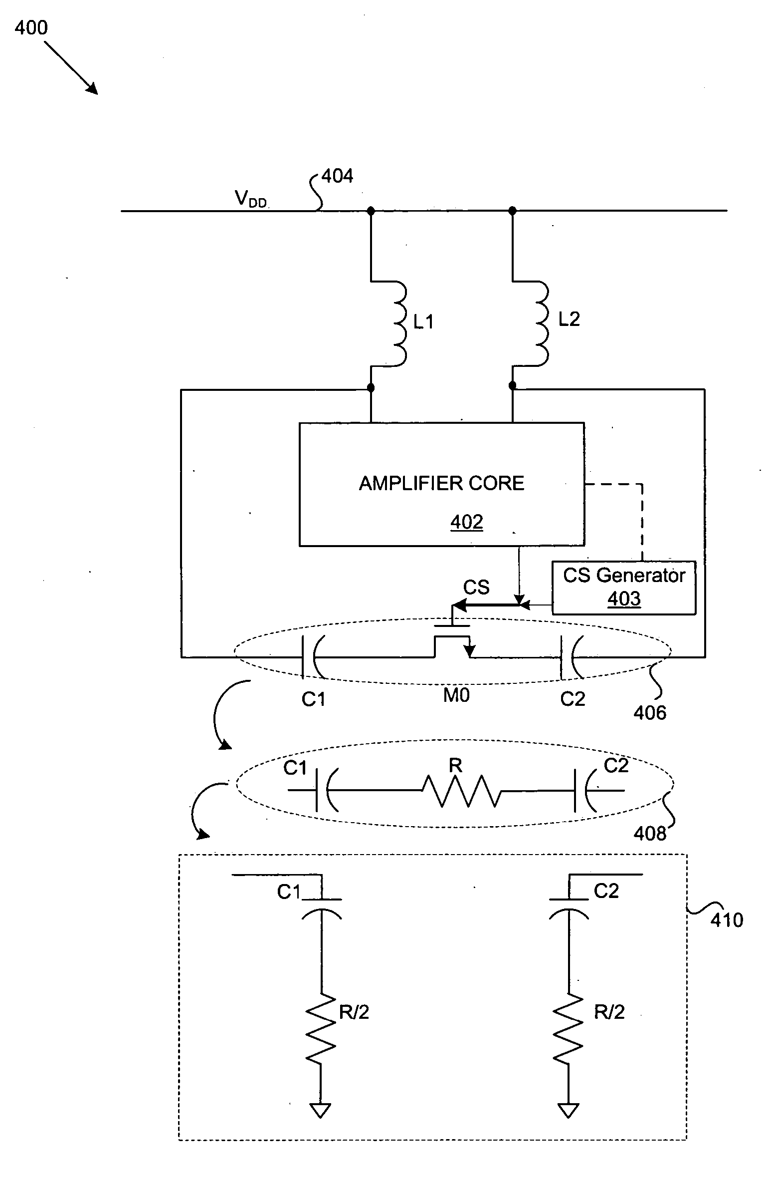
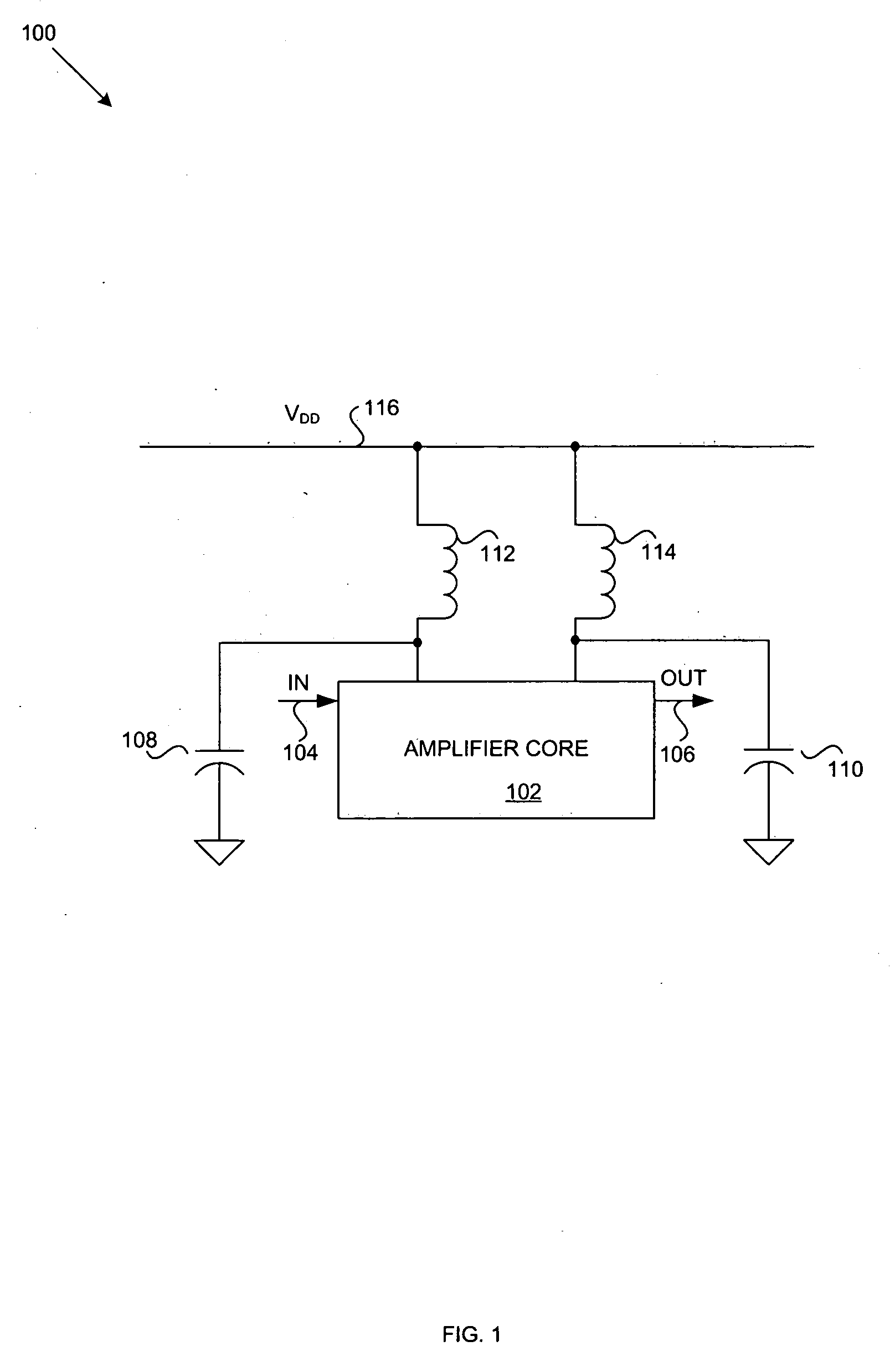
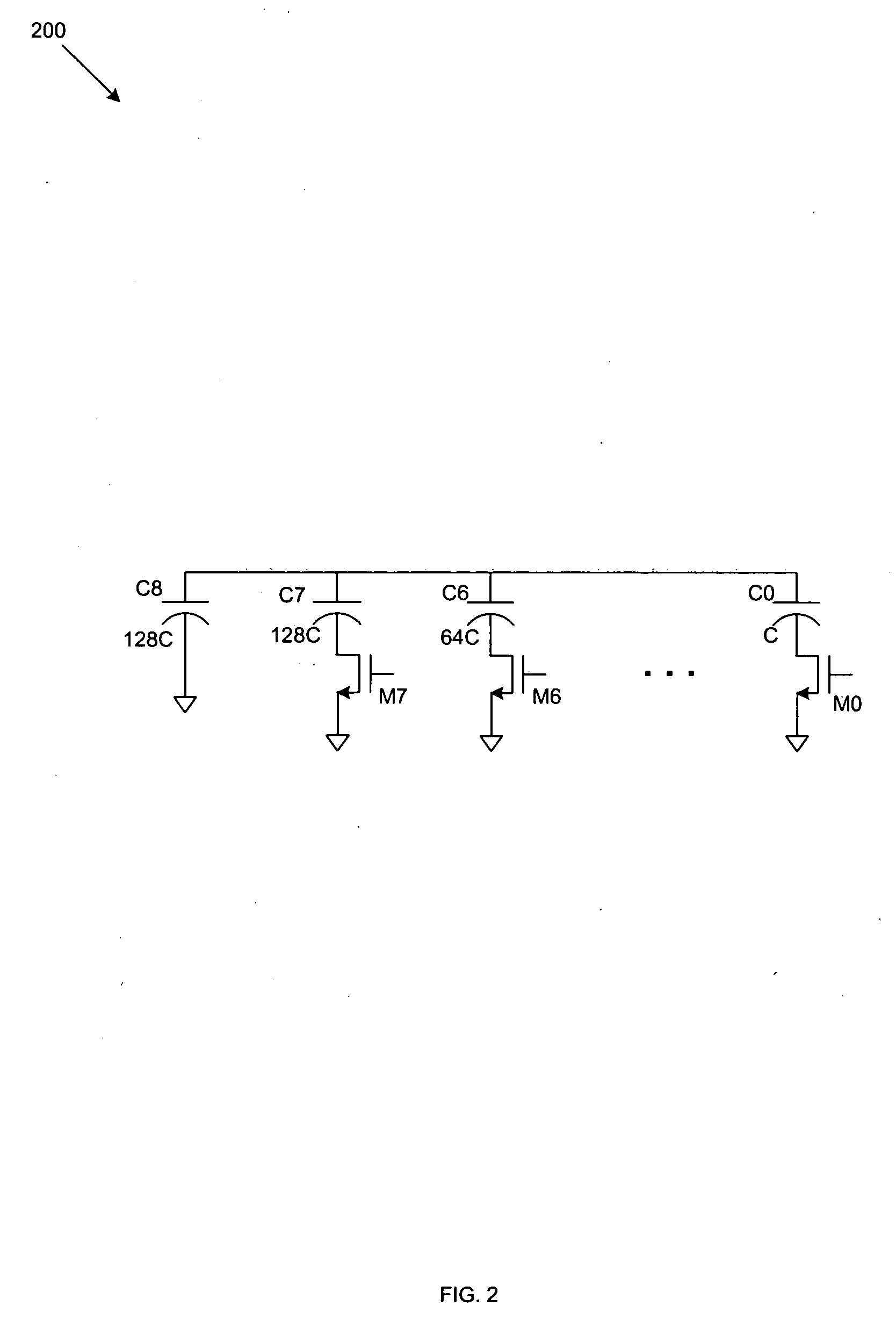
[0034] Certain aspects of the invention may be found in a method and system for increasing an amplifier circuit's Q factor. An amplifying device, such as a low noise amplifier (LNA), a power amplifier (PA), and / or a buffer, as well as an oscillator, such as a voltage controlled oscillator (VCO), may utilize one or more signal tuning circuits comprising one or more switched capacitors. For example, a VCO and / or an amplifying device may utilize an inductance-capacitance (LC) tank for tuning one or more signals, where a switch, such as an NMOS transistor, may be utilized to selectively turn ON and / or OFF the tuning LC tank.

[0035] In an exemplary embodiment of the invention, a VCO may be utilized within a radio frequency (RF) transceiver and one or more LC tanks may be utilized within the VCO to tune a differential output of the VCO. The VCO, and the corresponding differential output LC-tanks, may be adapted for tuning over a broad range of frequencies, such as from about 3.4 GHz to ab...


PUM


Abstract

Methods and systems for increasing an amplifier circuit's Q factor are disclosed herein. The method may comprise coupling a first LC tank to a source of a single switching transistor and coupling a second LC tank to a drain of the single switching transistor. A gate of the single switching transistor may be controlled by an amplifier core coupled to the first LC tank and the second LC tank. A resistance of the first LC tank and the second LC tank may be decreased by about one half, which increases the Q factor by about two. The gate of the single switching transistor may be controlled by a control signal generator coupled to the amplifier core. The first LC tank and/or the second LC tank may be tuned to a frequency of about 3.4 GHz to 4 GHz. The single switching transistor may comprise an NMOS transistor.

Description

RELATED APPLICATIONS [0001] This application is related to the following applications, each of which is incorporated herein by reference in its entirety for all purposes: [0002] U.S. patent application Ser. No. ______ (Attorney Docket No. 16149US01) filed ______, 2004; [0003] U.S. patent application Ser. No. ______ (Attorney Docket No. 16150US01) filed ______, 2004; [0004] U.S. patent application Ser. No. ______ (Attorney Docket No. 16151US01) filed ______, 2004; [0005] U.S. patent application Ser. No. ______ (Attorney Docket No. 16152US01) filed ______, 2004; [0006] U.S. patent application Ser. No. ______ (Attorney Docket No. 16153US01) filed ______, 2004; [0007] U.S. patent application Ser. No. ______ (Attorney Docket No. 16154US01) filed ______, 2004; [0008] U.S. patent application Ser. No. ______ (Attorney Docket No. 16155US01) filed ______, 2004; [0009] U.S. patent application Ser. No. ______ (Attorney Docket No. 16157US01) filed ______, 2004; [0010] U.S. patent application Ser...

Claims


Application Information

Patent Timeline
IPC IPC(8): H03B5/12
CPCH03B2200/005H03B5/1206H03B5/1265
Inventor DARABI, HOOMANLEETE, JOHN
Owner AVAGO TECH INT SALES PTE LTD
Why Eureka
Try Eureka