Method and system for converting engineering data into 3D modeling data

a technology of engineering data and modeling data, applied in the field of methods and systems for converting engineering data into three-dimensional (3d) modeling data, can solve the problems of lack of true dimensional accuracy, difficult visualization even for technically astute engineers and architects, and difficult to achieve the effect of quantitatively accurate representation or duplication of elements, easy animation and/or fusion

Inactive Publication Date: 2006-05-04
HNTB HLDG
View PDF13 Cites 13 Cited by
  • Summary
  • Abstract
  • Description
  • Claims
  • Application Information

AI Technical Summary

Benefits of technology

[0018] As mentioned above, another advantage of the present invention is that the models used for design visualization can be re-used in a public project by incorporation into presentation boards, videos, web sites, print literature, interactive multimedia—almost any delivery method. The present invention permits the models to be used in connection with simulation data in a traffic modeling package to present, in a highly accurate form, the movement of vehicles through a project, such as a toll plaza or an interchange.
[0019] In short, the present invention permits engineering data to be converted and used in a plurality of commercially available software packages for the creation of a host of three-dimensional effects including drive-throughs and fly-bys, exterior-to-interior transitions, character modeling, creation of natural elements, surface textures and materials, and a host of special effects from explosions to neon light emissions all in a quantitatively accurate representation or duplication of the elements under study. The resulting accurate 3D models can then easily be animated and / or merged with digital video.
[0020] Additionally, while the example given herein as an implementation of the present invention is in the architectural industry, the present invention is in no way limited to such an application. The present invention could be used in any setting where someone wishes to use available technically accurate engineering data generated in a computer aided design software application in a non-CAD software application, such as a 3D modeling software package to generate technically accurate photo realistic 3D models. For example, the present invention could be implemented in the avionics industry to assist with wing design.

Problems solved by technology

As the complexity of a project increases, visualization becomes difficult even for technically astute engineers and architects.
While artist's renderings can be beautiful and compelling, they often lack true dimensional accuracy.
Apart from being technically inaccurate, artist's renderings are rather time-consuming, expensive and do not lend themselves to frequent design changes.
Often these tools have some limited 3D visualization (rendering) capability built-in and are adequate to help the designer picture his / her design but are not up to the standards of quality and sophistication expected in the 3D graphic arts community.
The problem, however, is that the underlying file format of engineering software is generally not compatible with industry standard 3D modeling packages.
While TIN models are a generally acceptable method of representing designs, large or complex models create an overwhelming amount of data as x, y and z information is needed for each point in the model.
This large amount of data often exceeds the memory and processing capacity of even dedicated high-end computers frequently causing them to crash.
Additionally, the data from the engineering design software package is generally in a file format which is incompatible with 3D modeling packages, thereby making it unusable.
The resulting design created anew in the 3D modeling package does not make direct use of the data from the design created in the engineering design software package.
In this respect, the 3D modeling package operator is merely functioning like the artist in the aforementioned artist rendering scenario and is not able to directly use the electronic engineering data from the engineering design software package.
This duplication of effort is costly, time-consuming and reduces the accuracy of the resulting 3D model.

Method used


Image

  • Method and system for converting engineering data into 3D modeling data
  • Method and system for converting engineering data into 3D modeling data
  • Method and system for converting engineering data into 3D modeling data

Examples


Embodiment Construction

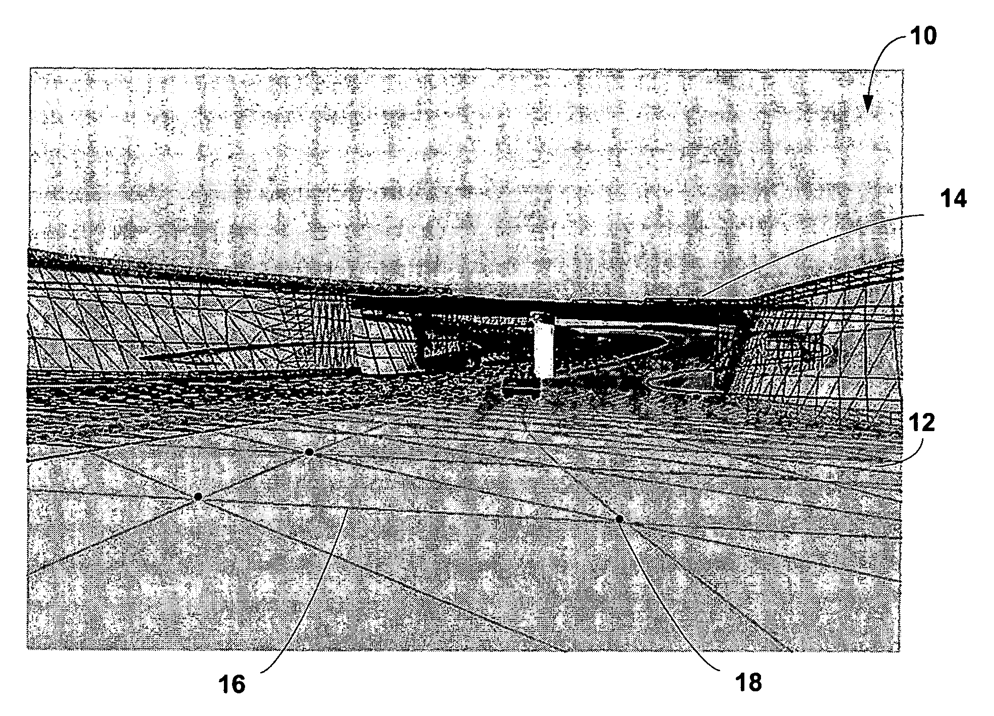
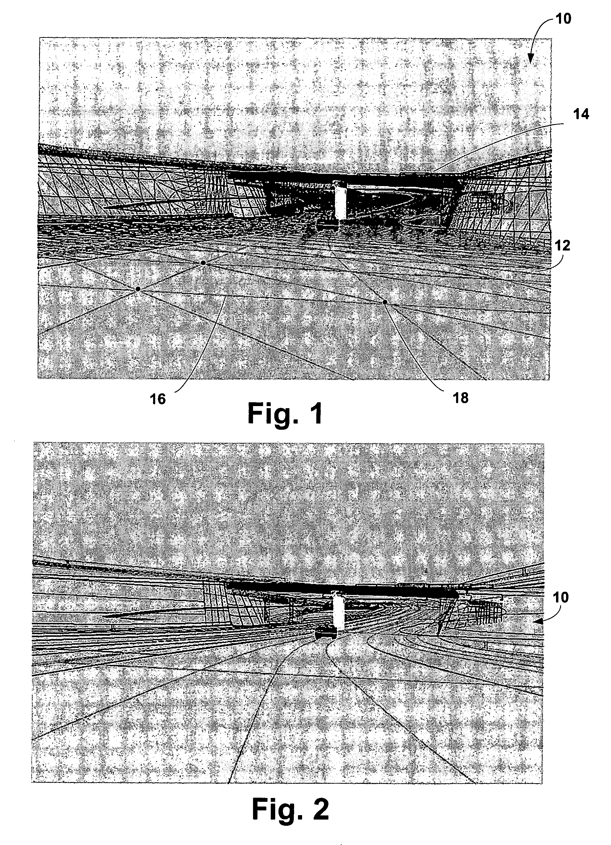
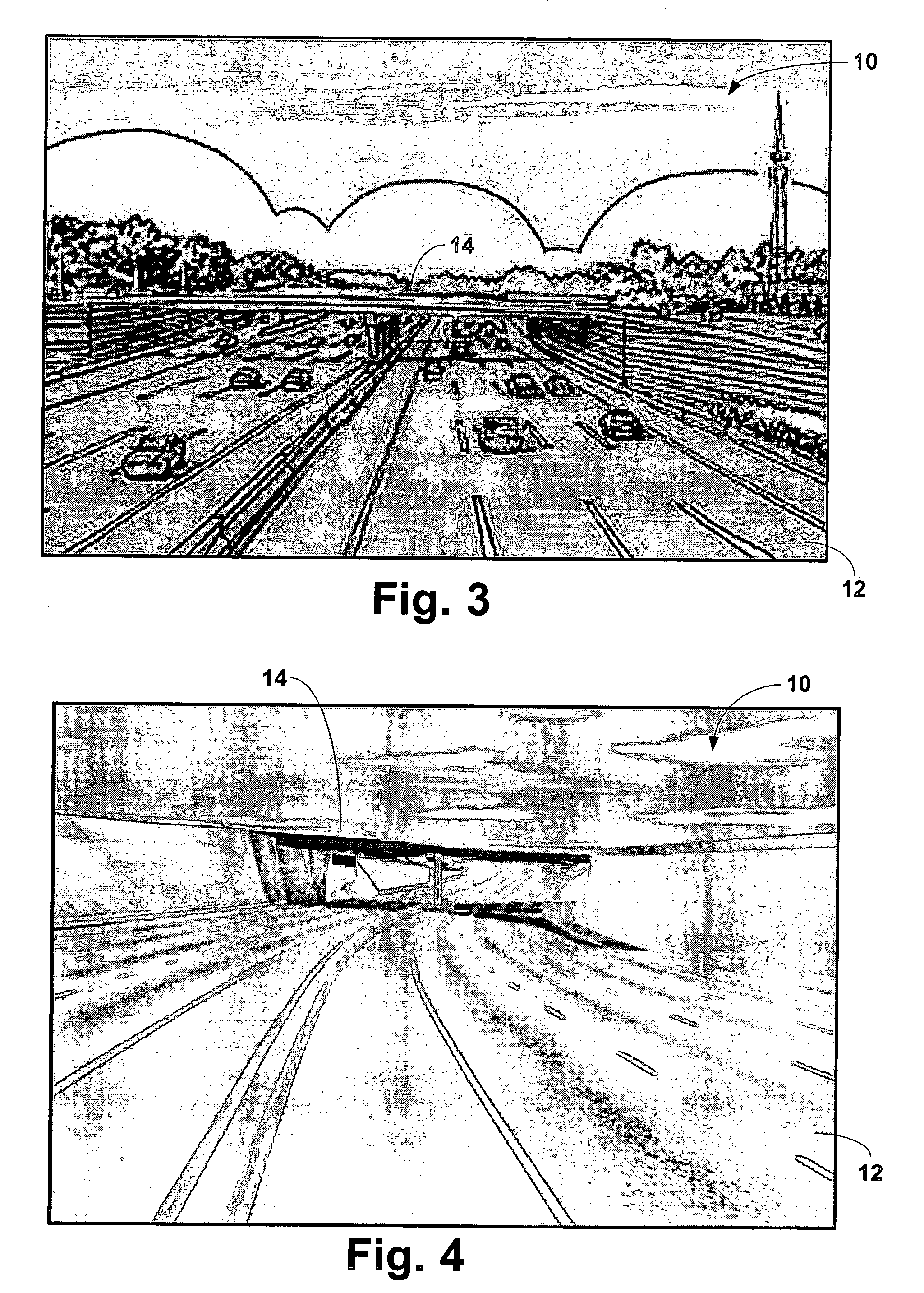
[0049] Referring now to the drawings in more detail and initially to FIG. 1, numeral 10 generally designates a design or project. The project 10 is a sunken roadway 12 with an overpass 14. In FIG. 1, the project 10 is illustrated by way of a traditional triangulated irregular network (“TIN”) model. As discussed above, a TIN consists of a plurality of non-overlapping triangles 16 which connect a plurality of points 18. Each of the points 18 has data associated therewith representing the points X, Y and Z coordinates. As is illustrated in FIG. 1, as the change in the terrain of the design 10 increases, the sizes of the associated triangles 16 decreases to permit the associated triangles 16 to represent the terrain changes. Consequently, as the level of changes in the terrain increases, the amount of data associated therewith increases. Each of the triangles 16 are wholly independent from one another in the respect that altering the orientation of one triangle does not change the orien...


PUM


Abstract

A system and method for converting data generated in an computer engineering design software component to an alternate format usable by a variety of alternate software components is provided. Engineering data from a project having a plurality of objects is provided. Objects are selected from the project for conversion and transportation to one of the alternate software components. The selected objects are converted to an alternate format, transported to the alternate software component and regenerated by the alternate software component in its own environment.

Description

CROSS-REFERENCE TO RELATED APPLICATIONS [0001] The present application is a continuation of U.S. application Ser. No. 10 / 653,479, entitled “METHOD AND SYSTEM FOR CONVERTING ENGINEERING DATA INTO 3D MODELING DATA”, which claims priority from U.S. Application Ser. No. 60 / 440,507, entitled “3D MODELING INTEGRATION SYSTEM”, filed Jan. 16, 2003.STATEMENT REGARDING FEDERALLY SPONSORED RESEARCH OR DEVELOPMENT [0002] Not applicable. BACKGROUND OF THE INVENTION [0003] The present invention relates to a method and system for converting engineering data into three-dimensional (3D) modeling data to permit the production of technically accurate 3D models. More particularly, this invention relates to a method by which a user can electronically convert technically accurate engineering data into an alternate and generally smaller but still technically accurate format, transport the converted data to a 3D modeling software component and have the 3D modeling software component create technically accu...

Claims


Application Information

Patent Timeline
Patent Type & Authority Applications(United States)
IPC IPC(8): G06T17/00G06FG06F1/00G06F17/50G06T17/40G09G5/00
CPCG06T17/00G06T2210/32G06T15/10
Inventor TROTTA, BRIAN W.WILLS, CHRISTOPHER C.URIBE, JUAN A.
Owner HNTB HLDG
Why Eureka
Try Eureka