Backlight unit and liquid crystal display with the same

Inactive Publication Date: 2006-05-04
LG DISPLAY CO LTD
View PDF10 Cites 95 Cited by
  • Summary
  • Abstract
  • Description
  • Claims
  • Application Information

AI Technical Summary

Benefits of technology

[0021] An object of the present invention is to provide a backlight unit that has a scattering plate formed of tempered glass, thereby improving light transmission and reliability of an LCD even under high tempe

Problems solved by technology

However, since the scattering plate formed of the PMMA has properties of a high coefficient of linear expansion and a low heat deformation temperature, it may be easily deformed under a high temperature/humidity environment.
The deformation of the scatt

Method used


Image

  • Backlight unit and liquid crystal display with the same
  • Backlight unit and liquid crystal display with the same
  • Backlight unit and liquid crystal display with the same

Examples


first embodiment

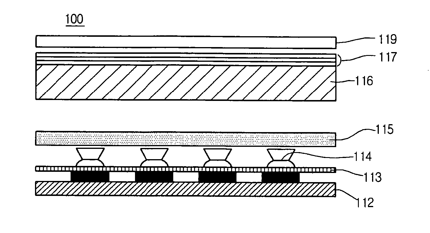
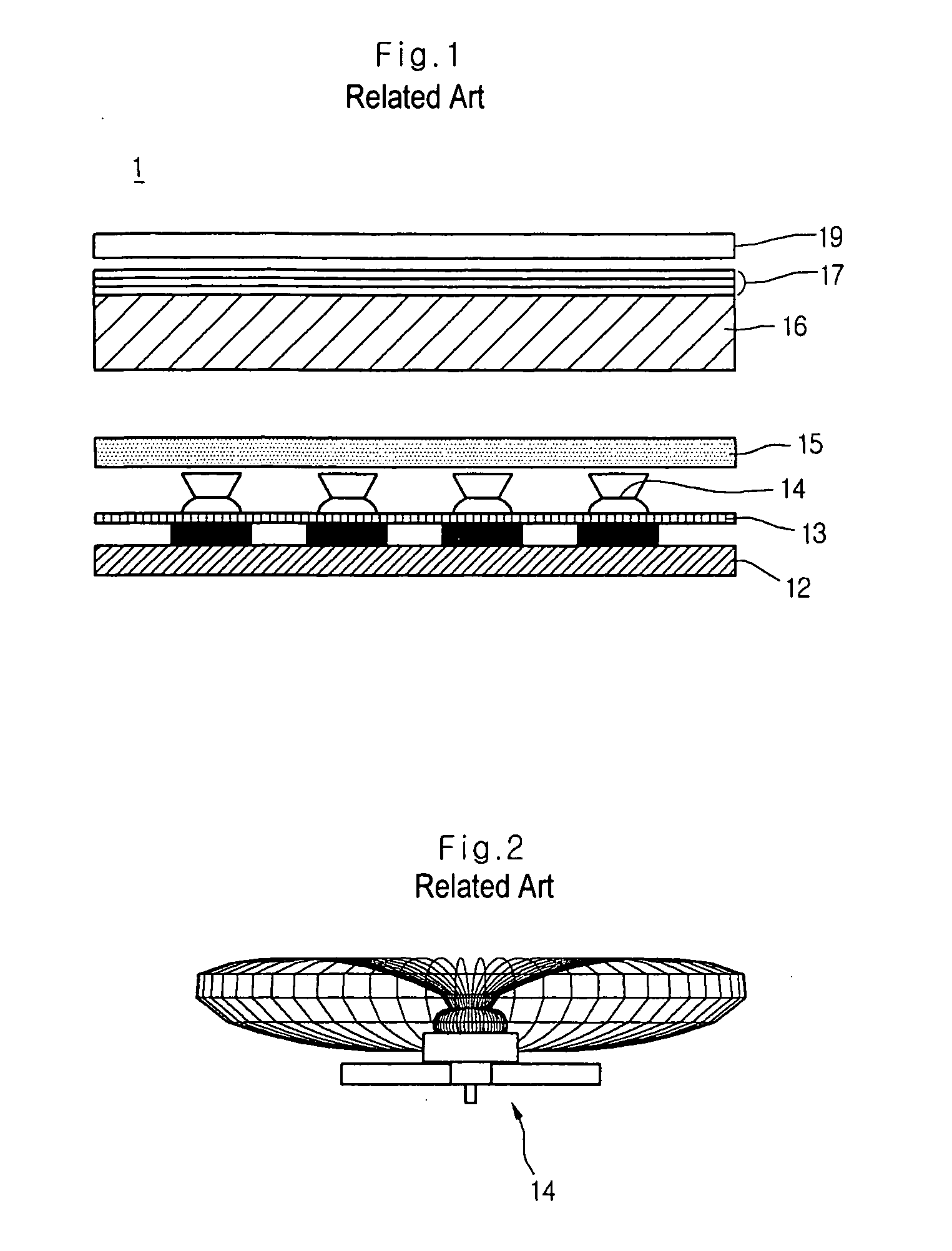
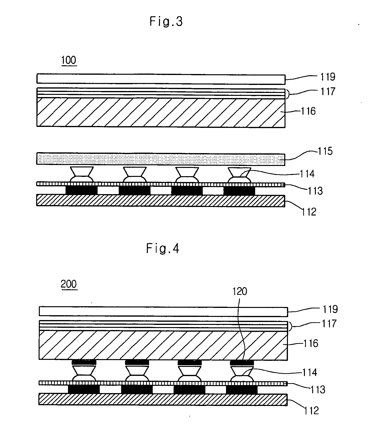
[0038]FIG. 3 shows an LCD with a backlight unit according to a first embodiment of the present invention.

[0039] Referring to FIG. 3, an LCD 100 of this embodiment includes a liquid crystal panel 119 having an upper substrate on which red, green and blue color filter layers and a black matrix are formed and a lower substrate on which pixel electrodes and thin film transistors (TFTs) are formed, and a backlight unit for supplying light to the liquid crystal panel 119. A liquid crystal layer is formed between the upper and lower substrates of the liquid crystal panel 119.

[0040] The backlight unit includes a transparent scattering plate 115 formed of tempered glass to scatter the light generated from a plurality of LEDs 114, and a diffusing plate 116 for diffusing the light that has passed through the scattering plate 115. A variety of optical sheets 117 are disposed on the diffusing plate 116. A reflecting plate 113 is disposed between the LEDs 114 and a MCPCB 112 for reflecting ligh...

second embodiment

[0053]FIG. 4 shows an LCD with a backlight unit according to a second embodiment of the present invention.

[0054] Since an LCD of this embodiment is similar to that of the first embodiment, only the different parts will be described hereinafter.

[0055] Referring to FIG. 4, a backlight unit for supplying light to a liquid crystal panel 119 includes a diffusing plate 116 for diffusing the light emitted from a plurality of LEDs 114, a diverter 120 disposed on a rear surface of the diffusing plate 116 to scatter the light emitted in the vertical direction, an optical sheet 117 disposed between the liquid crystal panel 119 and the diffusing plate 116, and a reflecting plate 113 disposed between the LEDs 114 and the MCPCB 112 for reflecting the light, which is directed toward the MCPCB 112, toward the liquid crystal panel 119.

[0056] The LEDs 114 are point light sources that emit red, green and blue lights, and can be side emitting type or other types.

[0057] The diverter 120 having one o...


PUM


Abstract

A backlight unit and a liquid crystal display device including such a backlight unit are provided. According to an embodiment, there is provided a backlight unit comprising a plurality of light emitting diodes (LEDs) for generating light, a printed circuit board (PCB) for controlling the LEDs, a transparent scattering plate provided with a scattering optical pattern for scattering the light from the LEDs, and a diffusing plate for diffusing the light scattered by the scattering plate.

Description

[0001] This application claims priority under 35 U.S.C. §119 on Patent Application No. 10-2004-0087582 filed on Oct. 30, 2004 in the Republic of Korea, the entire contents of which are hereby incorporated by reference. BACKGROUND OF THE INVENTION [0002] 1. Field of the Invention [0003] The present invention relates to a backlight unit that can reduce light losses that may be caused by leakage of the light to an external side. The present invention further relates to a liquid crystal display (LCD) with such a backlight unit. [0004] 2. Description of the Related Art [0005] In recent years, an LCD has increasingly gained attention as a flat display device that varies optical anisotropy by applying an electric field to liquid crystal having a fluidity property as well as a crystal optical property. Since the LCD is relatively slim, with low electric consumption and capability of being made in a large-sized display panel with a high definition, it has been widely used. [0006] Generally, ...

Claims


Application Information

Patent Timeline
IPC IPC(8): G02F1/1335
CPCG02F1/133603Y10S362/80G02F1/1335
Inventor PARK, HEE JEONG
Owner LG DISPLAY CO LTD
Why Eureka
Try Eureka