Light emitting module, optical head, and optical disc recording and reproducing apparatus

a technology of light emitting modules and optical heads, which is applied in the direction of lighting and heating apparatus, instruments, optical beam sources, etc., can solve the problems of limiting the finishing accuracy of sheet metal presses, terminals, and the inability to realize the miniaturization and thin-shape of integrated units b>9/b>, so as to reduce potential differences

Inactive Publication Date: 2006-05-04
PANASONIC CORP
View PDF11 Cites 8 Cited by
  • Summary
  • Abstract
  • Description
  • Claims
  • Application Information

AI Technical Summary

Benefits of technology

[0063] The 11th aspect of the present invention is the light emitting module according to the 1st aspect of the present invention, comprising a static protection mechanism, which makes it possible to put a space between two electrodes of said light source as said surface mount component into an electrically conductive state by solder, wiring or conductive component on said conductive multilayer substrate, and at the same time, to put a space between said two electro...

Problems solved by technology

However, in this configuration, there has been the following problem.
Because of the oversize of this resin package and the limit in the finishing accuracy of the sheet metal press composing the heat radiating plate 4, the terminal 5 and the like, to realize miniaturization and thin-shape of the integrated unit 9 becomes difficult.
Further, since heat conductivity of the resin also becomes low, heat dissipation by conduction through the resin package 6 from the heat radiating plate 4 is dif...

Method used


Image

  • Light emitting module, optical head, and optical disc recording and reproducing apparatus
  • Light emitting module, optical head, and optical disc recording and reproducing apparatus
  • Light emitting module, optical head, and optical disc recording and reproducing apparatus

Examples


first embodiment

[0216] A first embodiment of the present invention will be described below with reference to the drawings.

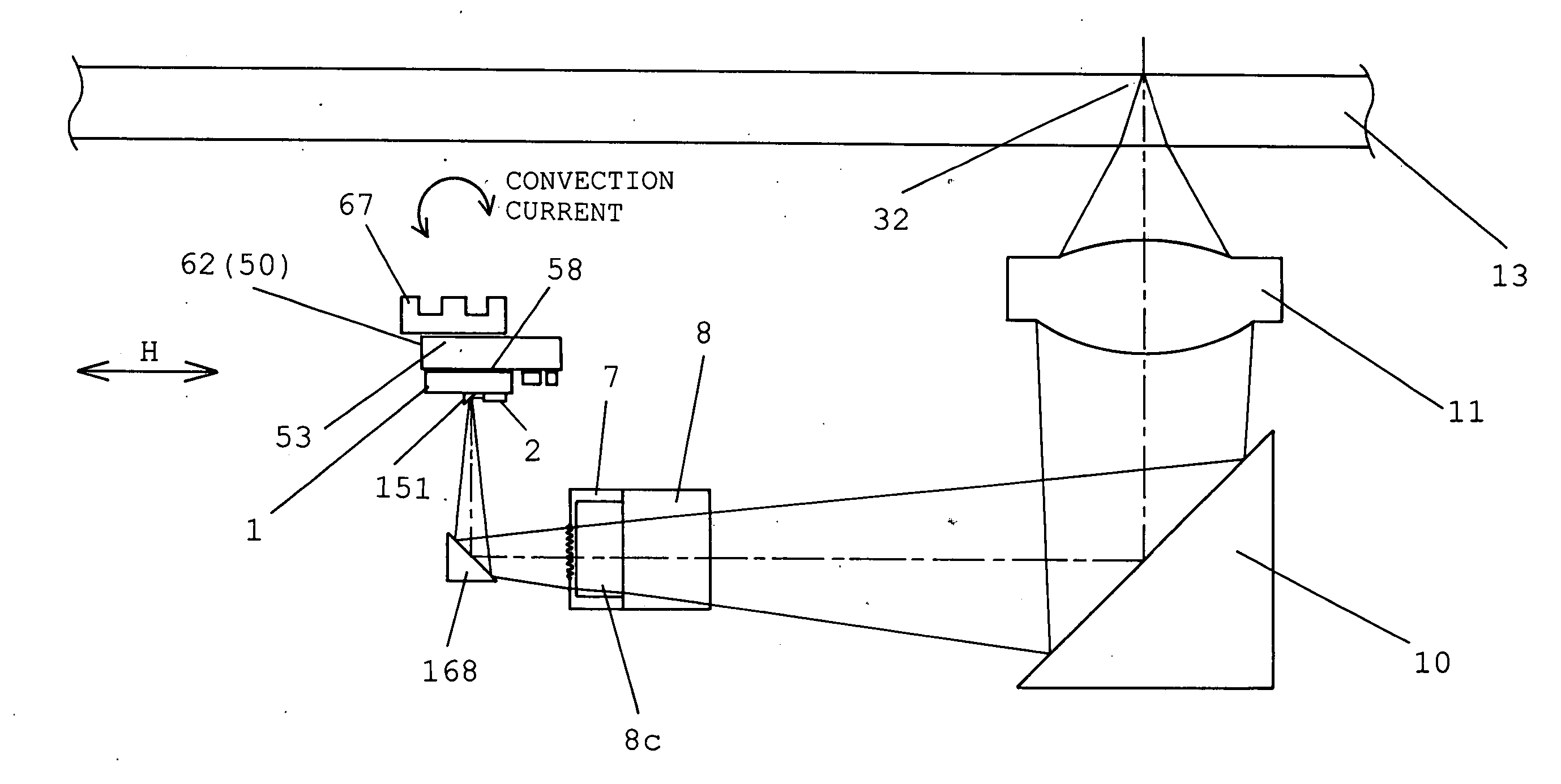
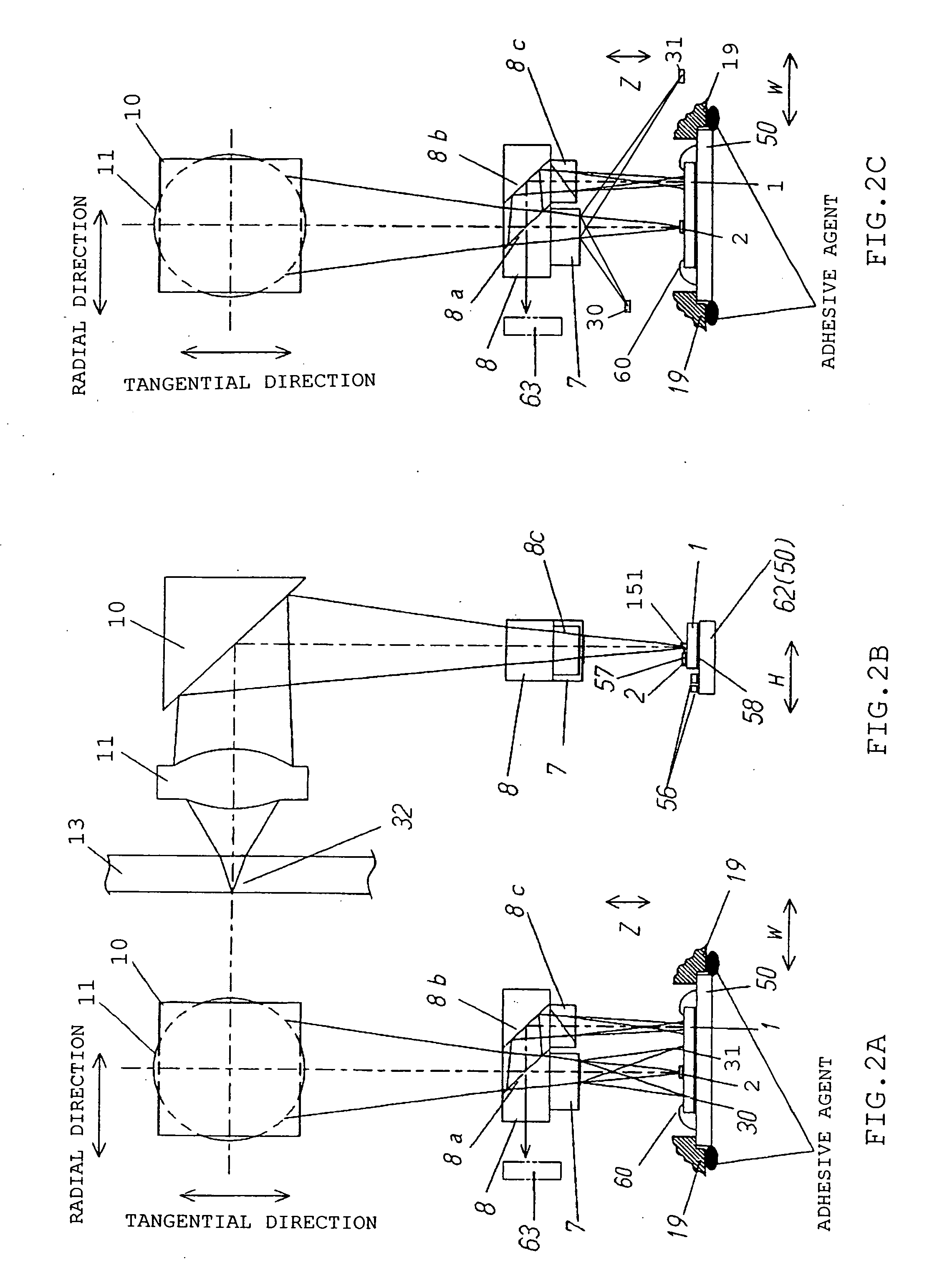
[0217]FIGS. 1, 2, 3, 4, 5, 6, 7, and 8 are block diagrams of the optical head of a first embodiment of the present invention and each unit constituting the optical head.

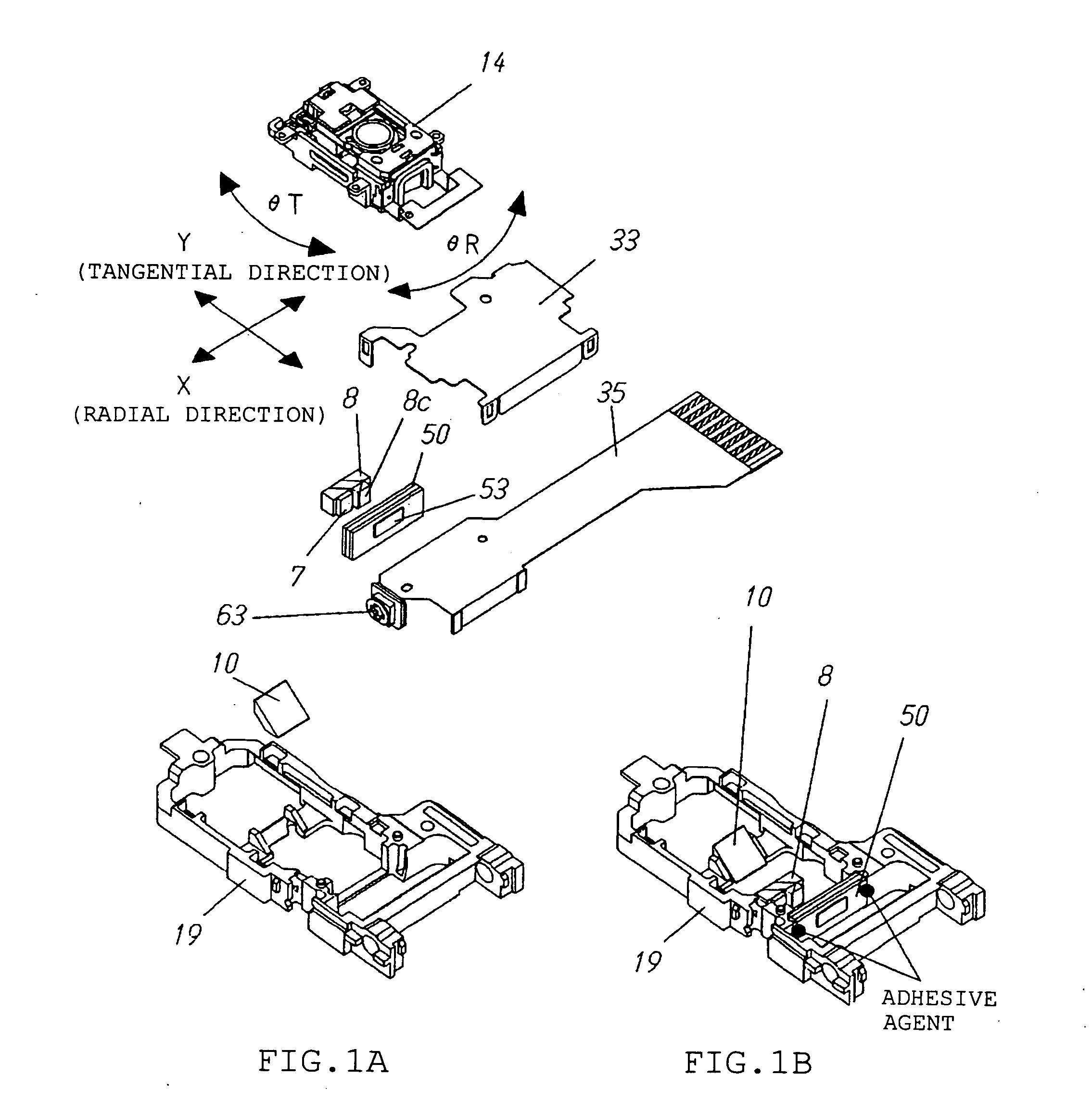
[0218]FIG. 1A is an exploded oblique view of the optical head, and FIG. 1B is its partial view.

[0219] In FIG. 1A, reference numeral 14 denotes an object lens driving device to drive an object lens 11 in focus and radial directions of a magneto-optical recording medium 13.

[0220]FIG. 3A is an exploded oblique view of the object lens driving device 14, and FIG. 3B is an oblique view showing its mounting state inside the optical head. As shown in FIG. 3A, the object lens driving device 14 is composed of parts of the optical lens 11 forming an optical spot on a magneto-optical recording medium 13 by using a light flux from a semiconductor laser 1, an optical lens holder 12, and a base 15, a suspension 16, a magnet...

second embodiment

[0292] Next, a second embodiment will be described with reference to FIGS. 11, 12, and 13. However, FIG. 11 is a circuit diagram showing a wiring state between a light receiving and emitting element module 62 and a flexible circuit 35, FIGS. 12A to 12C are three views showing a mounting state of each component in the light receiving and emitting element module 62, and FIGS. 13A and 13B are oblique views showing a mounting state of each component in the light receiving and emitting element module 62.

[0293] The present embodiment is different from the first embodiment in that the light receiving and emitting element module 62 is additionally mounted with an anti-static electricity filter 61, a high frequency filter 64, and a noise reduction condenser 65 on a multilayer ceramic substrate 50.

[0294] The surface of the multilayer ceramic substrate 50 is mounted with the anti-static electricity filter 61 comprising electronic parts such as a condenser or a coil (resister) or a filter, th...

third embodiment

[0300] Next, a third embodiment will be described with reference to FIGS. 14 and 15. However, FIGS. 14A and 14B is a circuit diagram showing a wiring state between a light receiving and emitting element module 62 and a flexible circuit 35, and FIGS. 15A and 15B are oblique views showing a mounting state of each component in the light receiving and emitting element module 62.

[0301] The present embodiment is difference from the first embodiment in that a light receiving element 63 for a laser monitor and a gain adjustment mechanism 66 are additionally mounted on the light receiving and emitting element module 62. The light receiving element 63 for the laser monitor is mounted on a silicon substrate 1 as a portion of a multisegment photodetector 3, and is means of detecting a light quantity emitted from the end surface opposing to the light emitting surface of a semiconductor laser 2. Further, the gain adjustment mechanism 66 is directly mounted on a multilayer ceramic substrate 50, a...


PUM


Abstract

A light emitting module used for an optical head having a light source and a single or plural light receiving elements and for using record or reproduce information on information recording medium includes a tabular conductive multilayer substrate; and at least a surface mount component mounted on the conductive multilayer substrate; the light emitting module includes at least the light source as the surface mount component.

Description

BACKGROUND OF THE INVENTION [0001] 1. Field of the Invention [0002] The present invention relates to a light emitting module and the like used in the optical head of a disc recording and reproducing apparatus, which is of the system projecting an optical spot on a disc recording medium and optically recording and reproducing information. [0003] 2. Related Art of the Invention [0004] In recent years, in general, a disc recording and reproducing apparatus has diversified its application for DVD recorders, MD, CD, and the like year by year, and has been increasingly gaining high density, miniaturization, high performance, high quality, and high-value added. Particularly, in the disc recording and reproducing apparatus utilizing a recordable medium, the demand for data and image recording has been on the rise, and miniaturization, thin-shape, high-performance, and high recording density have been ever-increasingly solicited. [0005] With respect to the conventional technology regarding t...

Claims


Application Information

Patent Timeline
IPC IPC(8): F21V29/00G11B7/12G11B7/125
CPCG11B7/1205H01L2224/48091H05K1/0206H05K1/0209H05K1/181H05K3/361H05K2201/09309H05K2201/09781H05K2201/10106H01L2224/73265H01L2224/49171H01L2224/48227H01L2224/45144H01L2224/32225G11B7/127H01L2924/00014H01L2924/00G11B7/121G11B7/123
Inventor NAKATA, HIDEKITOMITA, HIRONORIAIKOH, HIDEKINAGATA, TAKAYUKI
Owner PANASONIC CORP
Why Eureka
Try Eureka