

Push-pull inverter with snubber energy recovery
a technology of push-pull inverter and energy recovery, which is applied in the direction of power conversion systems, dc-dc conversion, electrical equipment, etc., can solve the problems of snubbing circuit, increasing the cost and size of inverter circuit, and reducing the efficiency of inverter circuits
- Summary
- Abstract
- Description
- Claims
- Application Information
AI Technical Summary
Benefits of technology
Problems solved by technology
Method used
Image

Examples
Embodiment Construction
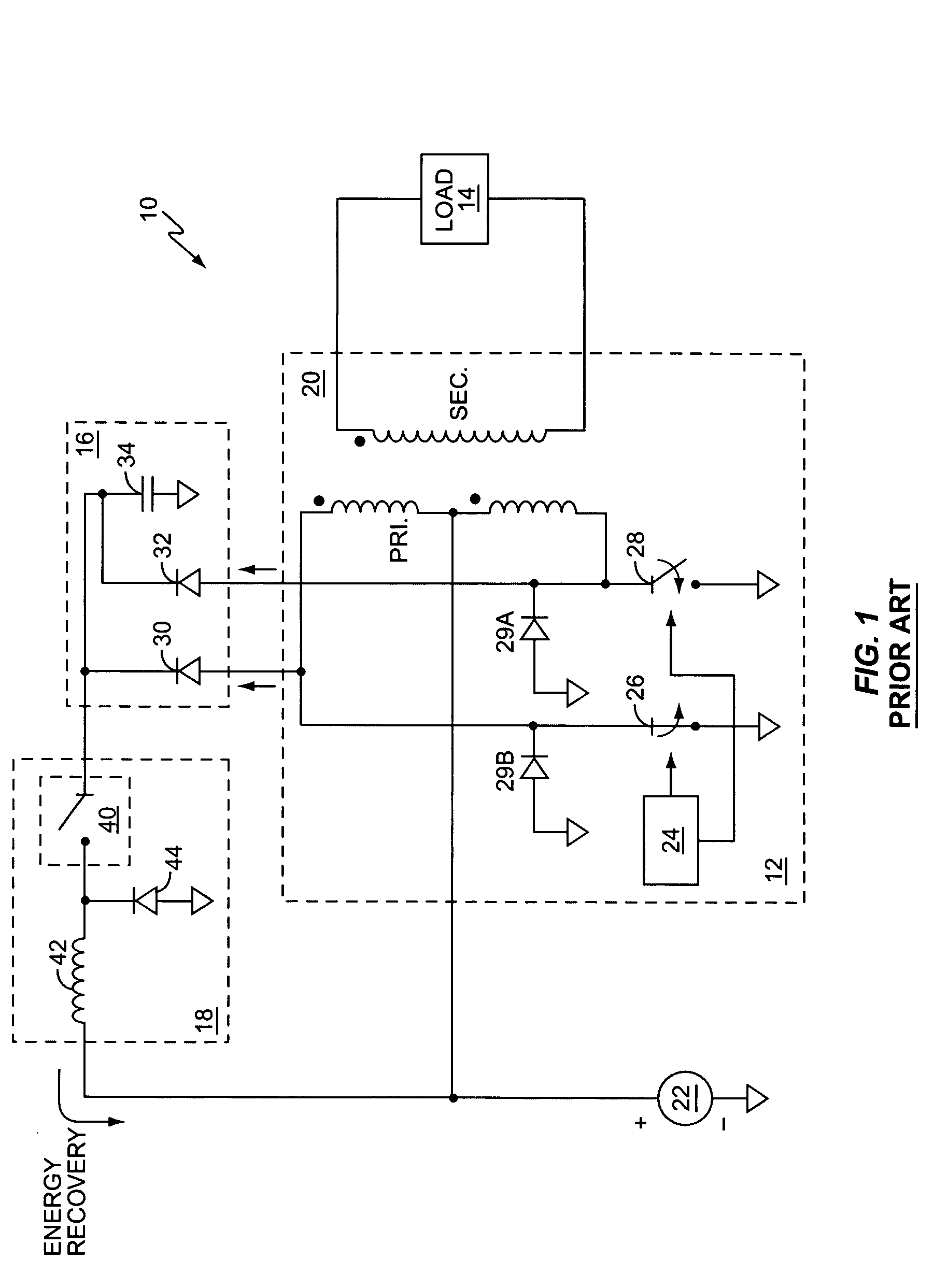
[0028]FIG. 1 is a diagram of a conventional power inverter 10 comprising a push-pull inverter circuit 12 coupled to a load 14, a snubber circuit 16, and a buck converter circuit 18 configured to enhance inverter efficiency by recovering a portion of the energy stored in the snubber circuit 16. In operation, an inverter transformer 20 is used to convert DC power from a DC supply 22 based on a switching controller 24 opening and closing main power switches 26 and 28.
[0029] As those skilled in the art will appreciate, an AC waveform of a desired voltage can be set up on the secondary winding of transformer 20 based on alternately switching power switches 26 and 28 on and off according to a desired duty cycle. The commutation of primary winding current from first and second halves of the center-tapped primary winding by operation of switches 26 and 28 is supported by the use of free-wheeling diodes 29A and 29B, as is understood by those skilled in the art.
[0030] The generation of volt...
PUM
 Abstract
Description
Claims
Application Information