High-power mode-locked laser device

Inactive Publication Date: 2006-05-04
CHROMAPLEX
View PDF8 Cites 31 Cited by
  • Summary
  • Abstract
  • Description
  • Claims
  • Application Information

AI Technical Summary

Benefits of technology

[0012] A non-linear optical medium, such as a glass plate, can be place inside the external cavity to broaden the emission frequency bandwidth of the gain elements. This can close any gaps in the emission spectrum. Alternatively or in addition, beam deflectors can be placed so as to intercept the individual beams emitted from the gain elements. The beam deflectors can change the angle of incidence of the individual optical beams onto the diffracting element, thereby changing an emission frequency or emission frequency range of the gain elements.

Problems solved by technology

However, the output power is limited by thermal considerations and induced facet damage at high output power density.
However, this approach has a limited optical peak power, because care has to be taken that the pulse energy does not cause catastrophic facet damage.

Method used


Image

  • High-power mode-locked laser device
  • High-power mode-locked laser device
  • High-power mode-locked laser device

Examples


Embodiment Construction

[0019] The system described herein is directed to arrays of gain elements, such as optical fibers, laser crystals, e.g. microlasers, and semiconductor lasers that are mode-locked in common in an external cavity and generate short optical pulses of high peak intensity. In particular, the system described herein uses phase matching between the cavity modes of different gain elements.

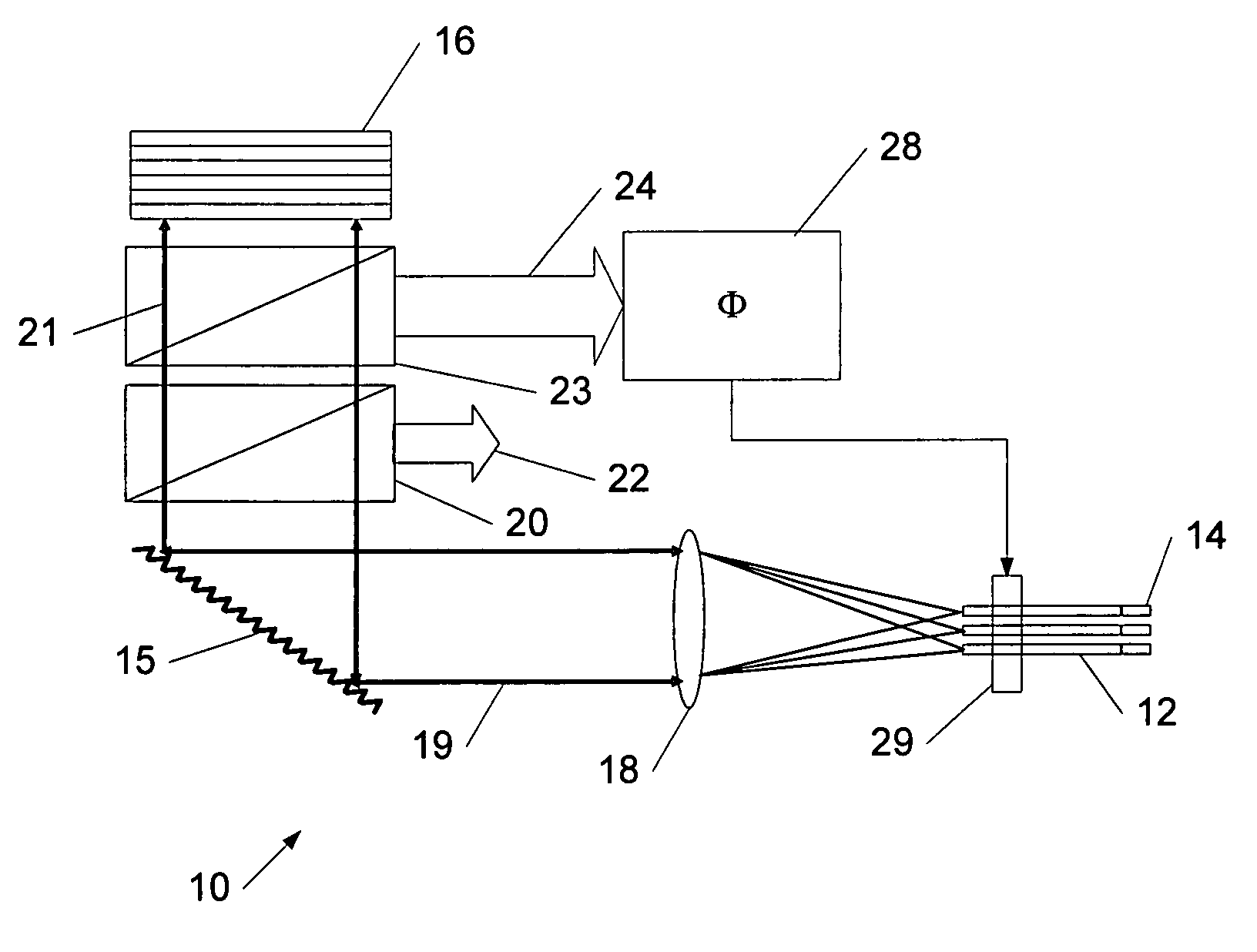
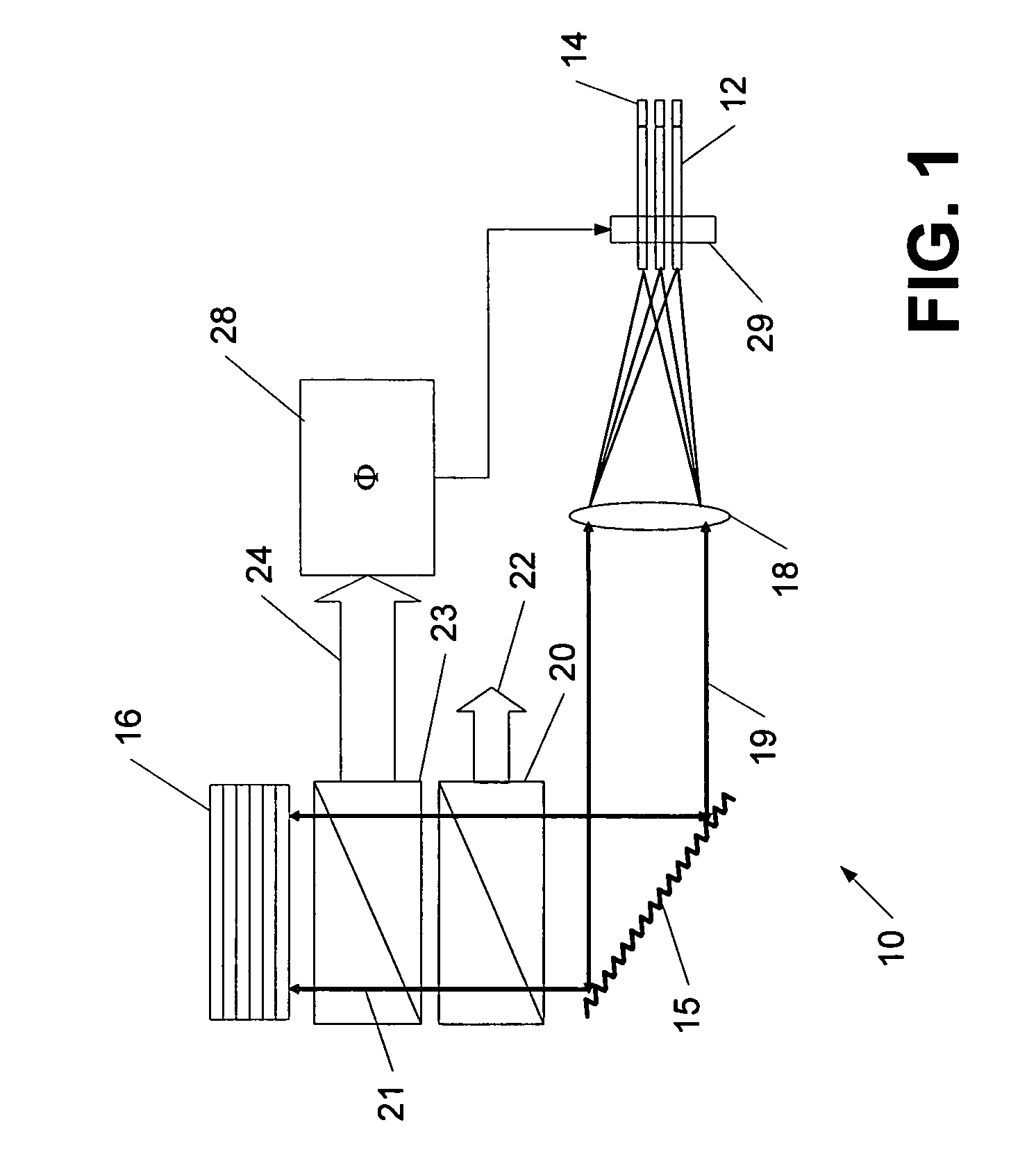
[0020]FIG. 1 shows schematically an exemplary mode-locked external cavity laser system 10 with an array of gain elements 12. In the depicted embodiment, the external cavity is formed by end mirrors 14 and a common semiconductor saturable absorber mirror (SESAM) 16 operating as a mode-locking device. Disposed inside the cavity is also a diffractive element (grating) 15 that diffracts the lasers beams 19 emitted by lasers 12 after collimation by a lens 18. Although the collimated laser beams 19 are shown in FIG. 1 as a single beam, the different collimated beams emitted by the different gain elements 12 wil...


PUM


Abstract

A mode-locked external cavity laser device includes a plurality of gain elements with corresponding end mirrors, and a diffracting element that diffracts optical beams emitted by the gain elements and combines the diffracted optical beams to form an overlapping output beam. A mode-locking device that intercepts the overlapping output beam and in cooperation with the end mirrors forms the external cavity. The mode-locking device mode-locks the optical beams from the gain elements in common and thus forms a mode-locked optical output beam of picosecond or femtosecond duration and high peak power.

Description

BACKGROUND OF THE INVENTION [0001] The invention relates to a laser device, and more particularly to an external cavity laser device with a plurality of gain elements producing a combined output beam of picosecond or femtosecond pulses with high peak power. [0002] Many applications require high-power lasers with a suitable pulse width and capable of a high repetition rate. In particular, there is an increasing need for high peak power and high average power picosecond and femtosecond lasers for many applications. These lasers are often used when it is required to take advantage of the non-linear interaction of high intensity optical pulses with matter. Non-linear interactions often occur when the focused optical field is raised to 108-1016 W / cm2 or more. In addition, when the pulse width of the laser is less than a few picoseconds, classical thermal transport effects are minimized. Non-linear optical effects include multi-photon absorption by molecules and non-thermal multi-photon i...

Claims


Application Information

Patent Timeline
IPC IPC(8): H01S3/098H01S3/08
CPCH01S3/08009H01S3/105H01S3/1118H01S3/1618H01S3/2383H01S3/1112H01S5/0609H01S5/141H01S5/143H01S5/4062H01S5/028
Inventor FRANKEL, ROBERT
Owner CHROMAPLEX
Why Eureka
Try Eureka