Orthopedic and dental implant devices providing controlled drug delivery

a technology of oral and dental implants and controlled drugs, which is applied in the direction of shoulder joints, surgical staples, therapy, etc., can solve the problems of loss of bone tissue at the interface with the prosthetic device, the loosening of the joint/prosthetic, and the end of the prosthetic implan

Inactive Publication Date: 2006-05-04
MICROCHIPS INC
View PDF99 Cites 254 Cited by
  • Summary
  • Abstract
  • Description
  • Claims
  • Application Information

AI Technical Summary

Benefits of technology

[0008] Improved implantable prosthetic devices are provided for controlled drug delivery. In one aspect, the device includes a prosthetic device body having at least one outer surface area; two or more discrete reservoirs located in spaced apart positions across at least a portion of the outer surface area, the reservoirs formed with an opening at the surface of the device body and extending into the device body; and a release system disposed in the reservoirs which comprises at least one therapeutic or prophylactic agent, wherein following implantation into a patient the therapeutic or prophylactic agent is released in a controlled manner from the reservoirs. The prosthetic device body preferably is a joint prosthesis or part thereof, such as a hip prosthesis, a knee prosthesis, a vertebral or spinal disc prosthesis, or part thereof. In another embodiment, the prosthetic device body comprises a surgical staple or surgical screw. In still another embodiment, the device body may comprise a dental implant or maxillofacial reconstruction device.

Problems solved by technology

Risks that may follow the replacement surgery include infection and, in the long term with some types of devices, loss of bone tissue at the interface with the prosthetic device as the bone remodels and consequent loosening of the joint / prosthetic.
Another drawback of joint replacement is that the prosthetic implant eventually will wear out, for example, ten to twenty years following implantation.
This is problematic where the patient receiving the joint replacement is relatively young and might be expected to live well beyond the useful life of the joint prosthetic.
Replacement of the prosthetic may not be possible in some instances, and would nevertheless require another invasive surgery.
Coatings, however, substantially limit the selection of the coating materials and the drugs, as well as substantially limiting the control over the release kinetics and spatial release patterns.
Unfortunately, coatings having improved mechanical stability and adhesion may tend to have decreased utility as a controlled drug delivery vehicle.
Surface coatings, however, are vulnerable to mechanical failure and suffer other limitations.
For instance, the choice of coating (drug formulation) material may be limited, because the material needs to be selected to yield a coating having sufficient structural integrity and adhesion properties.
Moreover, thin coatings typically provide little actual control over the release kinetics of drugs, due to the extremely short diffusion path of drug from / through the coating.
In addition, the use of a thicker coating can result in the creation of gaps between the prosthesis and the patient's tissue after the biodegradable matrix material of the drug formulation has degraded, which undesirably may permit differential motion between the prosthesis and adjacent tissue—and result in undesirable loosening of the prosthetic device.
Furthermore, not all drugs are suitable for controlled release from a surface coating, for example, certain drugs, e.g., due to their high aqueous solubility, are released from the coatings at an undesirably high rate and cannot remain localized for a therapeutically effective amount of time.

Method used


Image

  • Orthopedic and dental implant devices providing controlled drug delivery
  • Orthopedic and dental implant devices providing controlled drug delivery
  • Orthopedic and dental implant devices providing controlled drug delivery

Examples


Embodiment Construction

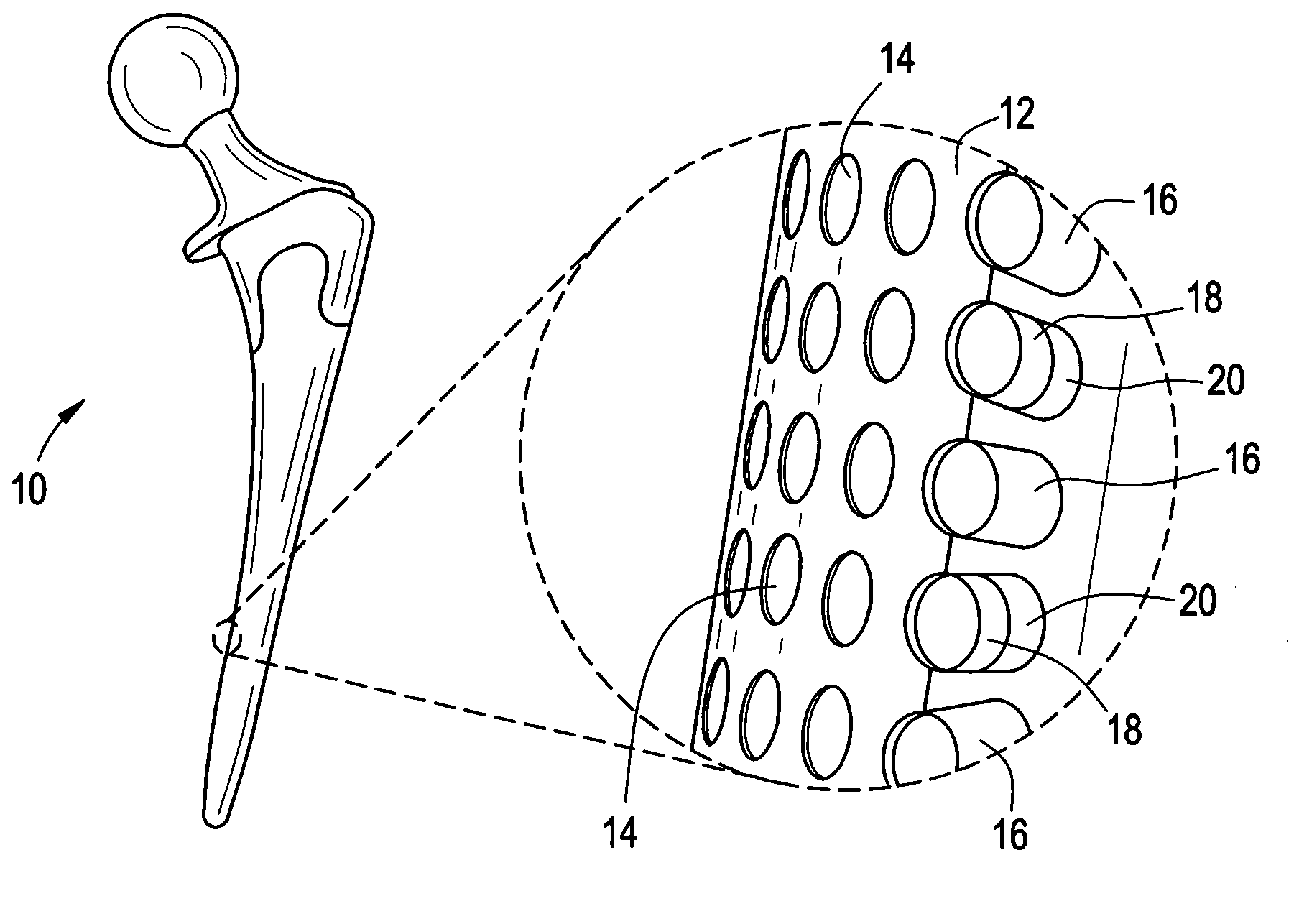
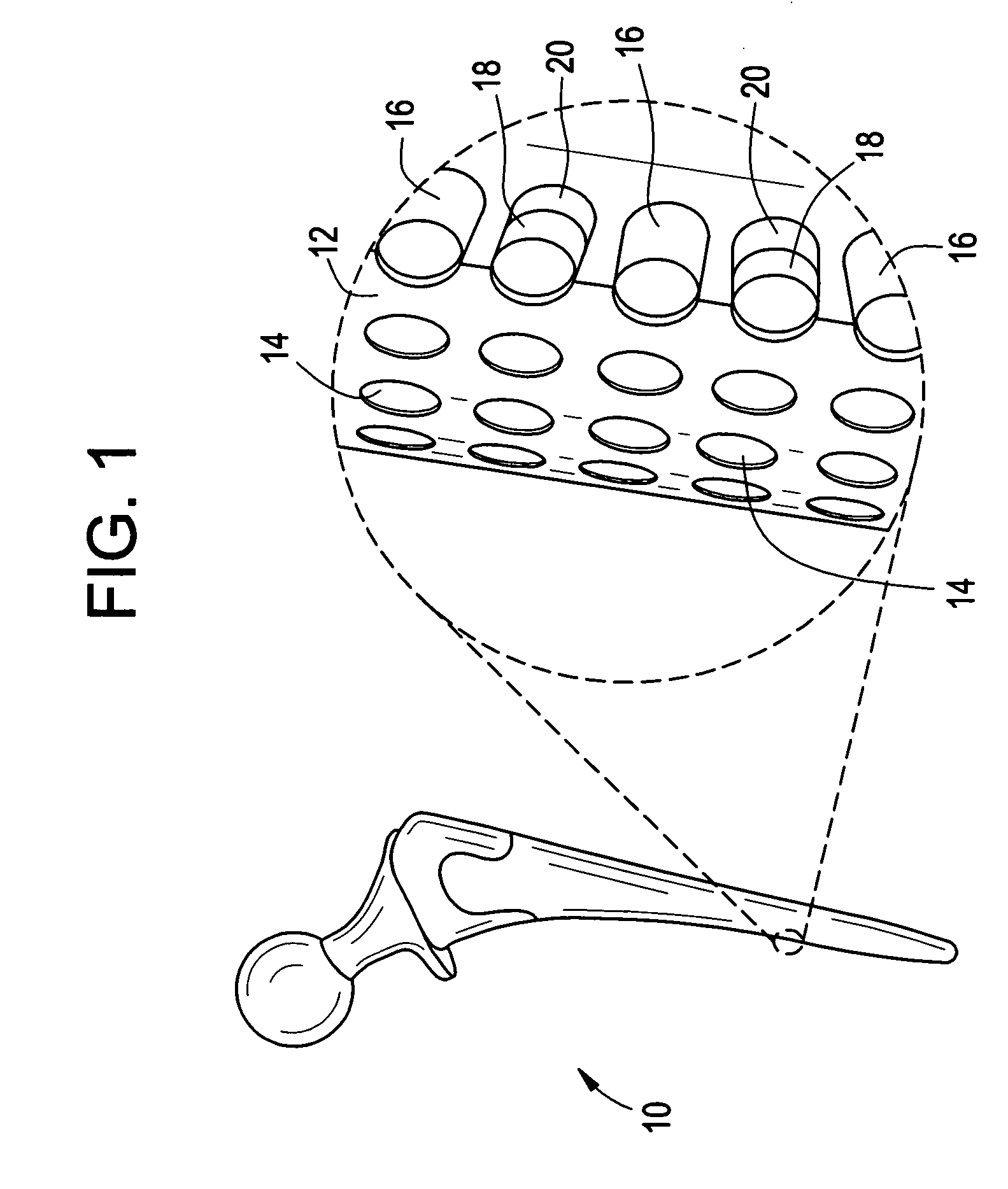
[0032] Implantable orthopedic, spinal, and dental devices, in particular prosthetic joint and prosthetic disc devices, have been developed to provide improved controlled release of drug at the site of implantation. The released therapeutic or prophylactic agents are primarily intended for local or regional effect, but may in certain embodiments be intended for systemic delivery.

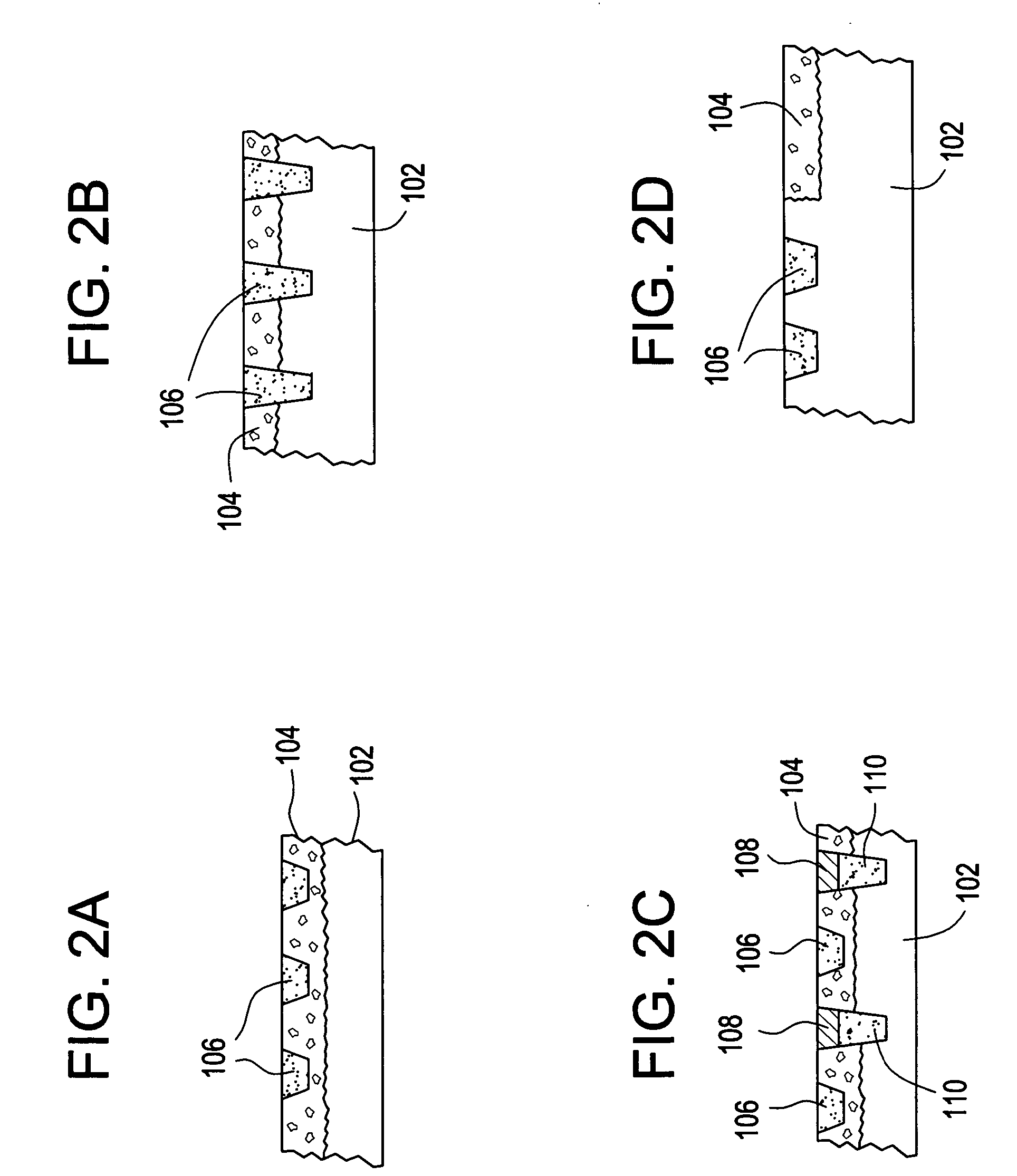
[0033] In one aspect, the device includes an array of discrete reservoirs (at least two and more preferably hundreds), particularly microreservoirs, that are provided across one or more outer surface areas of the device body. These reservoirs contain a release system comprising at least one therapeutic or prophylactic agent, and the release system and / or reservoir caps control the release kinetics (time and rate of release of the agent) in vivo following implantation. By containing the drug and controlled release formulation within discrete reservoirs built into (at least a portion of) the structure of the d...


PUM

PropertyMeasurementUnit
thicknessaaaaaaaaaa
thicknessaaaaaaaaaa
volumeaaaaaaaaaa

Abstract

Implantable prosthetic devices are provided for controlled drug delivery, for orthopedic and dental applications. The device may include a prosthetic device body having at least one outer surface area; two or more discrete reservoirs located in spaced apart positions across at least a portion of the outer surface area, the reservoirs formed with an opening at the surface of the device body and extending into the device body; and a release system disposed in the reservoirs which comprises at least one therapeutic or prophylactic agent, wherein following implantation into a patient the therapeutic or prophylactic agent is released in a controlled manner from the reservoirs. The prosthetic device body preferably is a joint prosthesis or part thereof, such as a hip prosthesis, a knee prosthesis, a vertebral or spinal disc prosthesis, or part thereof. Optional reservoir caps may further control release kinetics.

Description

CROSS-REFERENCE TO RELATED APPLICATIONS [0001] This application claims the benefit of U.S. Provisional Application No. 60 / 623,079, filed Oct. 28, 2004; U.S. Provisional Application No. 60 / 668,517, filed Apr. 5, 2005; and U.S. Provisional Application No. 60 / 670,487, filed Apr. 12, 2005. Those applications are incorporated herein by reference in their entirety.BACKGROUND OF THE INVENTION [0002] This invention is generally in the field of implantable medical and dental devices for controlled release of therapeutic and prophylactic agents into a human or animal patient, and particularly implants for replacing or augmenting bone, cartilage, or dental tissues. [0003] Approximately 180,000 hip replacements are performed each year in the United States. Artificial joints have become a common therapeutic option for replacing the structure of, and restoring function to, injured or diseased joints, including hips, knees, elbows, and shoulders. A few examples of these implantable prosthetic join...

Claims


Application Information

Patent Timeline
Patent Type & Authority Applications(United States)
IPC IPC(8): A61F2/28A61F2/02
CPCA61B17/0642A61B17/80A61B17/86A61B17/8625A61B2017/0648A61C8/0012A61C8/0016A61C19/063A61F2/30744A61F2/30767A61F2/30771A61F2/36A61F2/3662A61F2/367A61F2/3676A61F2/38A61F2/3804A61F2/3859A61F2/389A61F2/40A61F2/4425A61F2/446A61F2002/2817A61F2002/30013A61F2002/30032A61F2002/30036A61F2002/30062A61F2002/30064A61F2002/30075A61F2002/30224A61F2002/30324A61F2002/30326A61F2002/30677A61F2002/3068A61F2002/30787A61F2002/30808A61F2002/3081A61F2002/30838A61F2002/30878A61F2002/30929A61F2002/30971A61F2002/3611A61F2002/3625A61F2002/3631A61F2002/4631A61F2210/0004A61F2210/0061A61F2230/0069A61F2250/0024A61F2250/003A61F2250/0035A61F2250/0036A61F2250/0037A61F2250/0068A61F2310/00017A61F2310/00023A61F2310/00029A61F2310/00131A61F2310/00179A61L27/54A61L2300/406A61L2300/414A61L2300/604A61N1/30A61F2002/30011
Inventor CIMA, MICHAEL J.SANTINI, JOHN T. JR.STAPLES, MARK A.HUTCHINSON, CHARLES E.
Owner MICROCHIPS INC
Why Eureka
Try Eureka