
Method of engineering a property of an interface

Inactive Publication Date: 2006-05-04
HEWLETT PACKARD DEV CO LP
View PDF23 Cites 31 Cited by
  • Summary
  • Abstract
  • Description
  • Claims
  • Application Information

AI Technical Summary

Benefits of technology

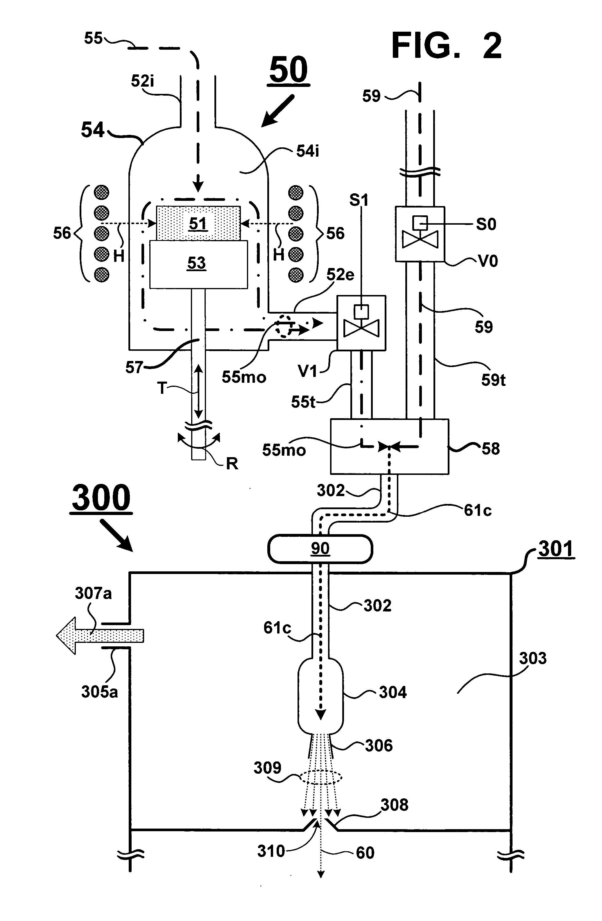
[0008] The present invention solves the aforementioned problems associated with manipulating the properties of an interface surface by combining a gas cluster ion beam apparatus (GCIB) with a source that generates a metal-organic gas that includes one or more metal-organic compounds. The metal-organic gas is combined in a carr

Problems solved by technology

Precise control of interface states is at present difficult to accomplish.
Interface topography and composition are nearly impossible to control and prior methods have only allowed gross manipulation of interface properties.
As device sizes decrease, undesirable surface anomalies at an interface are a major obstacle to producing devices with an economically acceptable yield.
Presently, one can try to prevent surface anomalies at an interface by deposition in an ultra high vacuum system; however, the use of the ultra high vacuum system results in high manufacturing costs and low manufacturing throughput.
However, for very thin layers of materials, uniform coverage is very difficult depending on the wetting characteristics of the material of the underlying layer.
For instance, many materials tend to form islands when deposited, which coalesce and grow, resulting in either a non-uniform layer or in a non-uniform topographical surface that is many monolayers thick.
Additionally, lattice mismatched materials create strain at the interface between thin film layers and the strain can result in columnar grain growth induced surface roughness.
True atomic layer growth is possible through molecular beam epitaxy (MBE); however, the range of materials that can be deposited using MBE is limited and MBE is a prohibitively expensive process.
For some materials ALD requires a water precursor, which can be destructive to device materials and / or properties, especially in materials that are susceptible to corrosion, such as the materials in a TMR junction.
Presently, site specific modification of an interface surface requires photolithographic or nano-imprinting processes and those processes can require several processing steps with each step having a potential to introduce a yield limiting defect.

Method used


Image

  • Method of engineering a property of an interface
  • Method of engineering a property of an interface
  • Method of engineering a property of an interface

Examples


Embodiment Construction

[0028] In the following detailed description and in the several figures of the drawings, like elements are identified with like reference numerals.

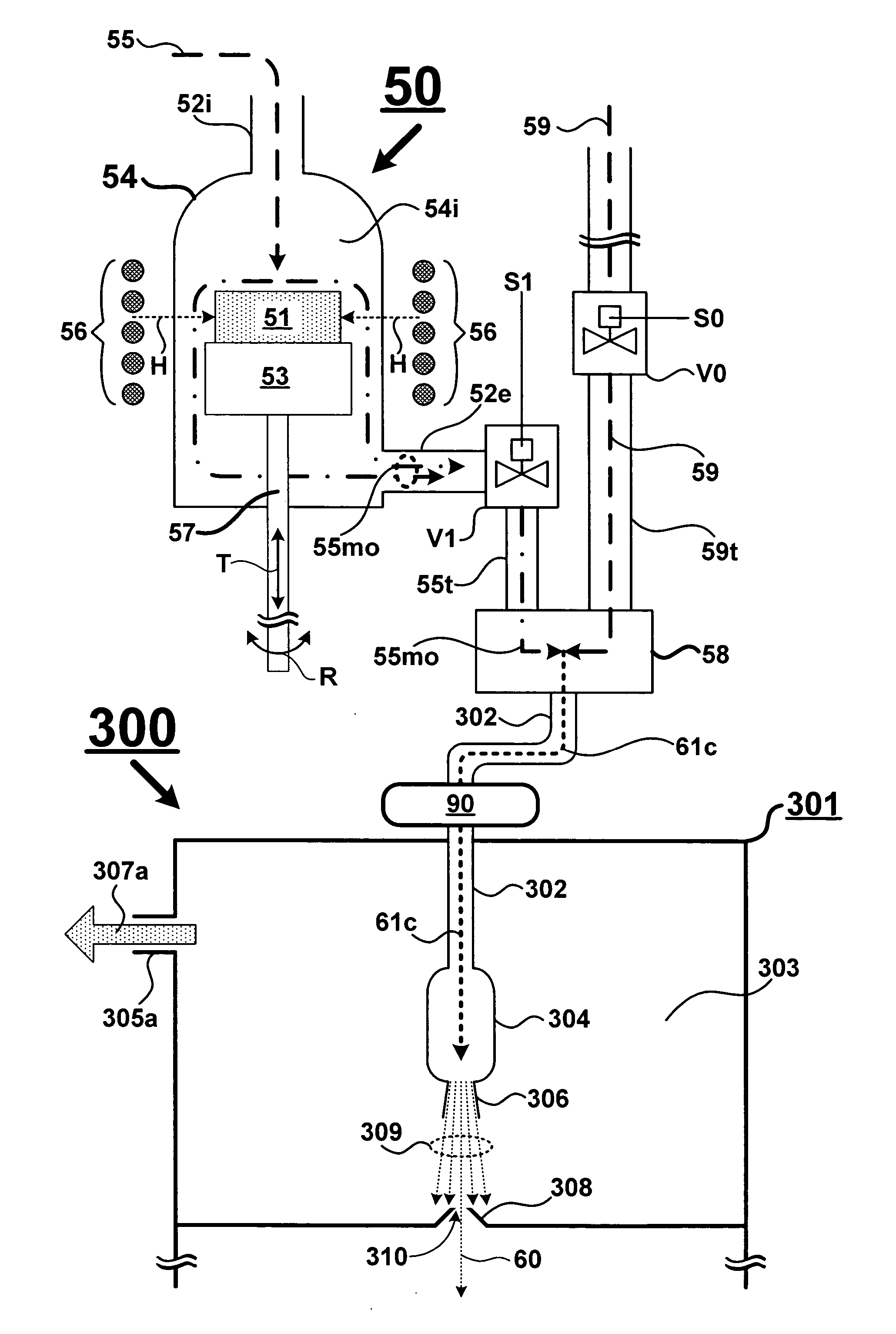
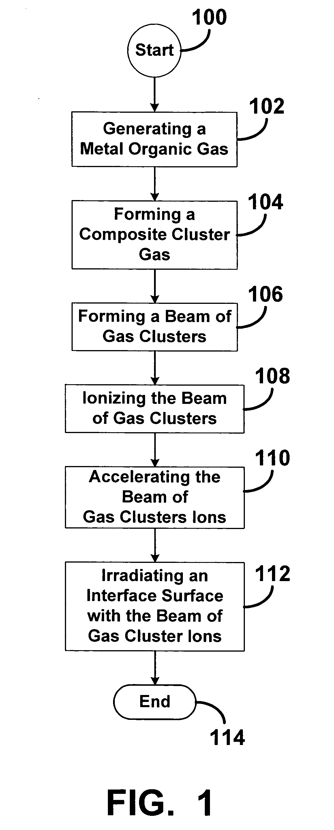
[0029] As shown in the drawings for purpose of illustration, the present invention is embodied in a method of engineering a property of an interface using a gas cluster ion beam apparatus. The method includes generating a metal-organic gas that includes at least one metal-organic compound, forming a composite gas by combining the metal-organic gas with a carrier gas and communicating the composite gas to the gas cluster ion beam apparatus, and forming a beam comprising a plurality of gas clusters from the composite gas. The gas clusters are ionized to form a beam of gas cluster ions that include the metal-organic compound. The gas cluster ions are accelerated and the beam irradiates an interface surface of a target material so that the gas cluster ions impact on the interface surface and disintegrate upon impact so that at least a portio...


PUM

PropertyMeasurementUnit
Concentrationaaaaaaaaaa
Adhesion strengthaaaaaaaaaa
Depthaaaaaaaaaa

Abstract

A method of engineering a property of an interface using a gas cluster ion beam (GCIB) apparatus is disclosed. The method includes introducing a metal-organic compound with a carrier gas to form a metal-organic gas and mixing the metal-organic gas with a cluster gas used in the GCIB. The GCIB forms a plurality of gas cluster ions that include the metal-organic compound, focuses the gas cluster ions into a beam, and then accelerates the beam towards an interface surface of a target material where the gas cluster ions impact on the interface surface and at least a portion of the metal-organic compound remain in contact with the interface surface and modifies a property of the interface surface. The metal-organic gas can include a plurality of metal-organic compounds.

Description

FIELD OF THE INVENTION [0001] The present invention relates generally to a method of engineering a property of an interface using a gas cluster ion beam apparatus and a metal-organic generator. More specifically, the present invention relates to a method of engineering a property of an interface by using a gas cluster ion beam apparatus and a source for generating a metal-organic compound in combination with each other to produce an ionized gas cluster beam that includes any of a variety of elements that can be produced from a metal-organic compound precursor. BACKGROUND ART [0002] Interface effects are becoming increasingly more important in device engineering. Examples of devices that depend on precise control of an interface between adjacent layers of thin film materials include sensors, semiconductor devices, photonic devices, MEMS devices, and magnetoresistance devices (e.g. MRAM). Generally, as devices geometries become smaller, interface properties becomes a larger considerat...

Claims


Application Information

Patent Timeline
IPC IPC(8): C23C14/00B05C11/00C23C16/00
CPCC23C14/06C23C14/48H01J2237/0812
Inventor NICKEL, JANICE H.
Owner HEWLETT PACKARD DEV CO LP
Learn More