Fluid occluding devices and methods

a technology of occluding devices and fluids, which is applied in the field of fluid occluding devices, can solve the problems of significant restenosis of arteries and often worse, and achieve the effects of improving mixing with residual arterial blood, improving the effect of flushing solution, and increasing the turbulence of flushing solution

a technology of occluding devices and fluids, which is applied in the field of fluid occluding devices, can solve the problems of significant restenosis of arteries and often worse, and achieve the effects of improving mixing with residual arterial blood, improving the effect of flushing solution, and increasing the turbulence of flushing solution

US20060095065A1Inactive Publication Date: 2006-05-04LIGHTLAB IMAGING

Image

  • Fluid occluding devices and methods
  • Fluid occluding devices and methods
  • Fluid occluding devices and methods

Examples


Embodiment Construction

[0033] The following description refers to the accompanying drawings that illustrate certain embodiments of the present invention. Other embodiments are possible and modifications may be made to the embodiments without departing from the spirit and scope of the invention. Therefore, the following detailed description is not meant to limit the present invention. Rather, the scope of the present invention is defined by the appended claims.

[0034] It should be understood that the order of the steps of the methods of the invention is immaterial so long as the invention remains operable. Moreover, two or more steps may be conducted simultaneously or in a different order than recited herein unless otherwise specified.

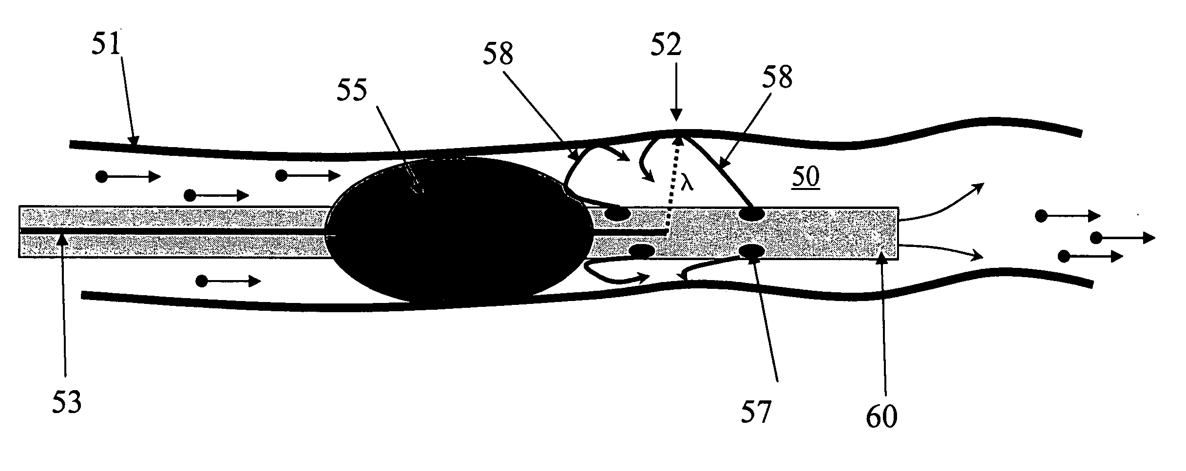
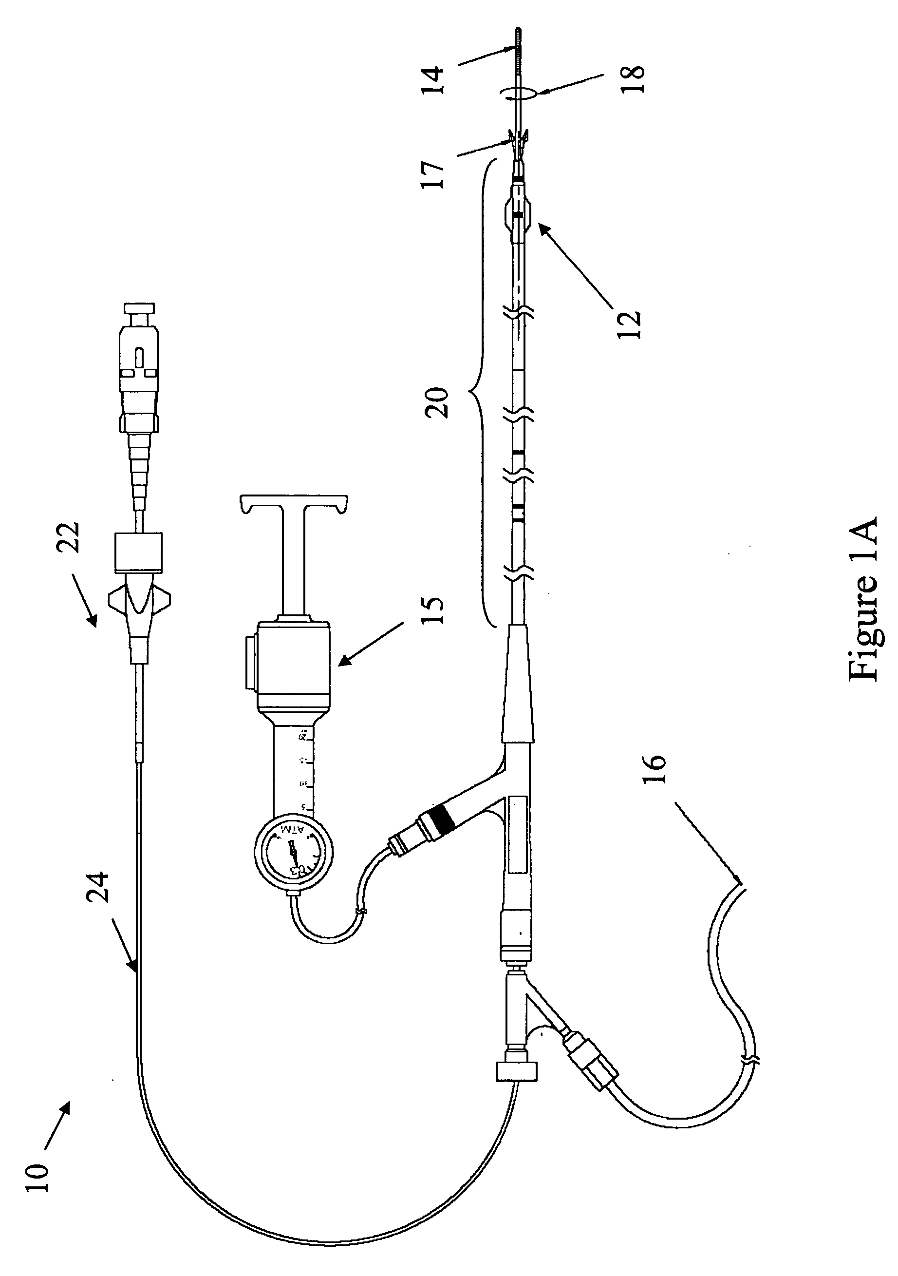
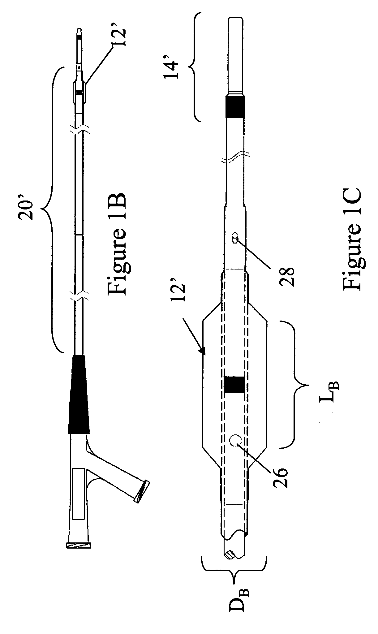
[0035] The balloons typically used in cardiac applications and other in vivo imaging systems are compliant balloons. A compliant balloon is analogous to a toy balloon. For a compliant balloon, greater pressure results in a greater increase in the size of the balloon. Also, w...


PUM


Abstract

In one aspect, the invention relates to a method of occluding blood in a blood vessel during the imaging of a portion of the blood vessel. The method includes the steps of selecting an inflatable element such that diameter of the inflated inflatable element is greater than the diameter of the blood vessel being imaged, introducing the inflatable element into the blood vessel and underinflating the inflatable element such that the vessel wall is not substantially deformed by the inflatable element, the inflatable element substantially occluding the blood vessel to reduce imaging distortion resulting from vessel fluids.

Description

RELATED APPLICATION [0001] This application claims priority to U.S. Provisional Application 60 / 613,062 filed on Sep. 24, 2004, the disclosure of which is herein incorporated by reference in its entirety.FIELD OF THE INVENTION [0002] The invention relates generally to the field of fluid occluding devices suitable for use in a human or animal. Specifically, the invention relates to catheters, inflatable elements and occluding methods suitable for use with an imaging system such as an Optical Coherence Tomography system. BACKGROUND OF THE INVENTION [0003] Optical Coherence Tomography (OCT) is a tomographic optical imaging modality that can produce high resolution (1-15 μm) tomographic images with a depth penetration of 1 to 2 mm in most tissues. OCT is used in medical applications, most notably ophthalmology, but also in oncology and cardiology. In vivo imaging of the walls of coronary vessels has been successfully performed many times by various groups. However, the primary factor lim...

Claims


Application Information

Patent Timeline
04 May 2006
Publication
US20060095065A1
IPC
A61M29/00; A61F2/958
CPC
A61B5/0066; A61B5/6852; A61B5/6853; A61M2025/1052
Inventors
TANIMURA, TETSUAKI; LEE, CHRISTOPHER