
Nonlinear receiver model for gate-level delay caculation

a receiver model and gate-level delay technology, applied in the field of electronic design automation, can solve the problems of increasing the model delay error, the inability to model the behavior of a signal at a receiver by a single (static) capacitance value, and the conventional cell receiver model is inadequate for the timing analysis of modern ic designs, so as to improve the accuracy of receiver modeling and increase the size of the cell library or analytical complexity.

Active Publication Date: 2006-05-04
SYNOPSYS INC
View PDF23 Cites 6 Cited by
  • Summary
  • Abstract
  • Description
  • Claims
  • Application Information

AI Technical Summary

Benefits of technology

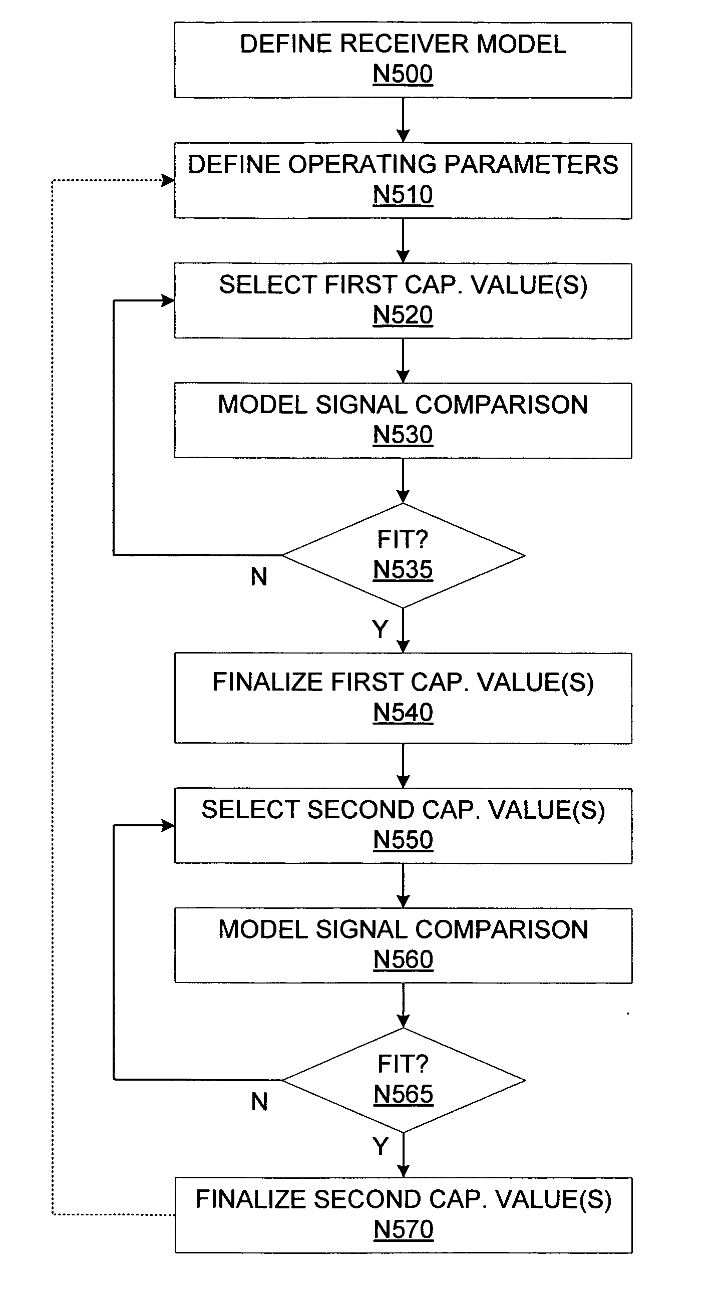
[0028] To improve receiver modeling accuracy without unduly increasing cell library size or analytical complexity, a multi-capacitance receiver model can be used. For example, in one embodiment, the static capacitor used in conventional receiver models can be replaced by a two-stage non-linear capacitor. The two-stage non-linear capacitor provides a first capacitance value while the receiver model is generating a first portion of a model receiver signal, and then switches to a second capacitance value when the model receiver signal reaches a predetermined switching voltage. In other embodiments, the non-linear capacitor can switch between three or more capacitance values.
[0031] The matching of the model receiver signal portions to the actual receiver signal portions can be performed using receiver input signals or receiver output signals. Furthermore, instead of matching timing characteristics such as delay and slew, the matching operation can compare the profiles of the model receiver signal portions and the corresponding actual receiver signal portions. In another embodiment, greater accuracy (i.e., a closer fit to the actual signal profile) can be achieved by increasing the number of different capacitance values assigned to the non-linear capacitor during generation of the model receiver signal.

Problems solved by technology

Unfortunately, as device sizes continue to shrink, the behavior of a signal at a receiver can no longer be modeled by a single (static) capacitance value, as dynamic effects (e.g., the Miller Effect) begin to affect the signal shape.
Unfortunately, while the model capacitance can be adjusted to reduce the slew error, such as in model signals S_INR-ST2 and S_INR-ST3, any such adjustment increases the model delay error.
Thus, conventional cell receiver models can be inadequate for the timing analysis of modern IC designs.

Method used


Image

  • Nonlinear receiver model for gate-level delay caculation
  • Nonlinear receiver model for gate-level delay caculation
  • Nonlinear receiver model for gate-level delay caculation

Examples


Embodiment Construction

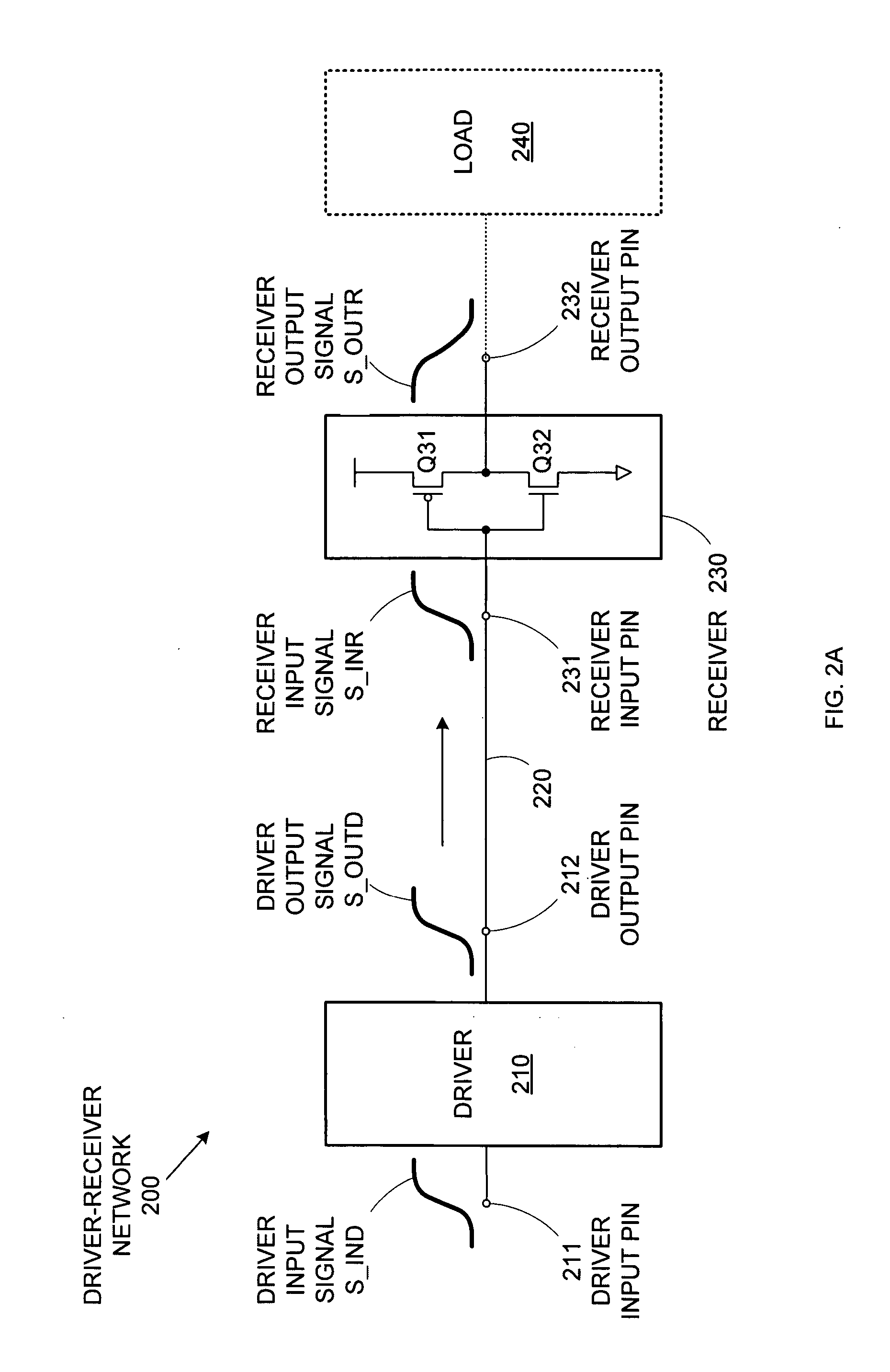
[0046] Because of the various dynamic effects that become more significant as device geometries are reduced in size, conventional single-capacitance receiver models used in EDA systems can no longer provide accurate timing simulations. FIG. 4A shows a multi-capacitance receiver model that overcomes this deficiency.

[0047]FIG. 4A models driver-receiver network 200 shown in FIG. 2A by replacing receiver 230 with a cell receiver model 430-NL that includes a resistor R_NL and a non-linear capacitor C_NL serially coupled between receiver input pin 231 and ground. Like cell receiver model 230-ST shown in FIG. 3A, cell receiver model 430-NL generates a model receiver input signal S_INR-NL in response to driver output signal S_OUTD provided by driver cell 210.

[0048] However, unlike static capacitor C_ST in cell receiver model 230-ST, non-linear capacitor C_NL in cell receiver model 430-NL does not provide a single, static capacitance over an entire signal transition. Rather, non-linear cap...


PUM


Abstract

A characterized cell library for EDA tools includes receiver model data that provides two or more capacitance values for a given receiver modeling situation (signal type and operating conditions). The receiver model can then use different capacitance values to generate different portions of the model receiver signal, thereby enabling more accurate matching of actual receiver signal timing characteristics. For example, a two-capacitance receiver model can be generated by using the first capacitance value to match the delay characteristics of an actual receiver, and by using the second capacitance (in light of the use of the first capacitance) to match the slew characteristics of that actual receiver. Because typical EDA timing analyses focus mainly on delay and slew (and not the detailed profile of circuit signals), a two-capacitance receiver model can provide a high degree of accuracy without significantly increasing cell library size and computational complexity.

Description

BACKGROUND OF THE INVENTION [0001] 1. Field of the Invention [0002] The invention is in the field of electronic design automation (EDA), and more particularly, is related to receiver models for that enable accurate timing analyses. [0003] 2. Related Art [0004] An electronic design automation (EDA) system is a computer software system used for designing integrated circuit (IC) devices. The EDA system typically receives one or more high level behavioral descriptions of an IC device (e.g., in HDL languages like VHDL, Verilog, etc.) and translates (“synthesizes”) this high-level design language description into netlists of various levels of abstraction. A netlist describes the IC design and is composed of nodes (functional elements) and edges, e.g., connections between nodes. At a higher level of abstraction, a generic netlist is typically produced based on technology independent primitives. [0005] The generic netlist can be translated into a lower level technology-specific netlist base...

Claims


Application Information

Patent Timeline
IPC IPC(8): G06F17/50G06F9/45
CPCG06F17/5031G06F17/5036G06F30/3312G06F30/367
Inventor LEVY, HAROLD J.
Owner SYNOPSYS INC
Learn More