Data center topology with transparent layer 4 and layer 7 services

Inactive Publication Date: 2006-05-04
CISCO TECH INC
View PDF5 Cites 145 Cited by
  • Summary
  • Abstract
  • Description
  • Claims
  • Application Information

AI Technical Summary

Benefits of technology

[0004] One problem with the topology of the n-tier data center is that it requires too many physical devices, is expensive to set up and operate and is difficult to manage. Thus setting up an n-tier data center to service requests from a large number of users is not only expensive but also difficult to maintain. What is needed is a simplified data center topology that reduced the number of physical devices, is inexpensive to set up and easy to maintain.
[0005] To address this need, an embodiment of a prior art data center is shown in FIG. 2 with a simplified topology. In this prior art embodiment, a firewall eliminates the need for a separate physical firewall device at more than one tier. Thus, as shown in FIG. 2, a single virtual firewall 28 interfaces a plurality of content switches 29-31, web servers 32, application servers 33 and database servers 34 to router 25. Virtual Local Area Networks or VLANs 35-37 couple the servers 32, 33 and 34, and the respective content switches 29-31 to firewall 28. Traffic from a server, such as one web server 32 to a database server 34 will pass through firewall 28 to be routed to database server 34 by router 25. The traffic must pass through firewall 28 a second time before reaching database servers 34 thereby providing secure communication between servers coupled to different VLANs. While this embodiment reduces the number of devices, it is still expensive to set up and maintain. Thus, by replacing the multiple firewalls 10, 17, and 22 shown in FIG. 1 with a single firewall 28, the data center topology in FIG. 2 provides the same functionality but with considera

Problems solved by technology

One problem with the topology of the n-tier data center is that it requires too many physical devices, is expensive to set up and operate and is difficult to manage.
Thus setting up an n-tier data center to service requests from a large number of users is not only expensive but also difficult to maintain.
While this embodiment reduces the number of devices, it is still expensive to set up and maintain

Method used


Image

  • Data center topology with transparent layer 4 and layer 7 services
  • Data center topology with transparent layer 4 and layer 7 services
  • Data center topology with transparent layer 4 and layer 7 services

Examples


Embodiment Construction

[0016] In the description herein for embodiments of the present invention, numerous specific details are provided, such as examples of components and / or methods, to provide a thorough understanding of embodiments of the present invention. One skilled in the relevant art will recognize, however, that an embodiment of the invention can be practiced without one or more of the specific details, or with other apparatus, systems, assemblies, methods, components, parts, and / or the like. In other instances, well-known structures, materials, or operations are not specifically shown or described in detail to avoid obscuring aspects of embodiments of the present invention.

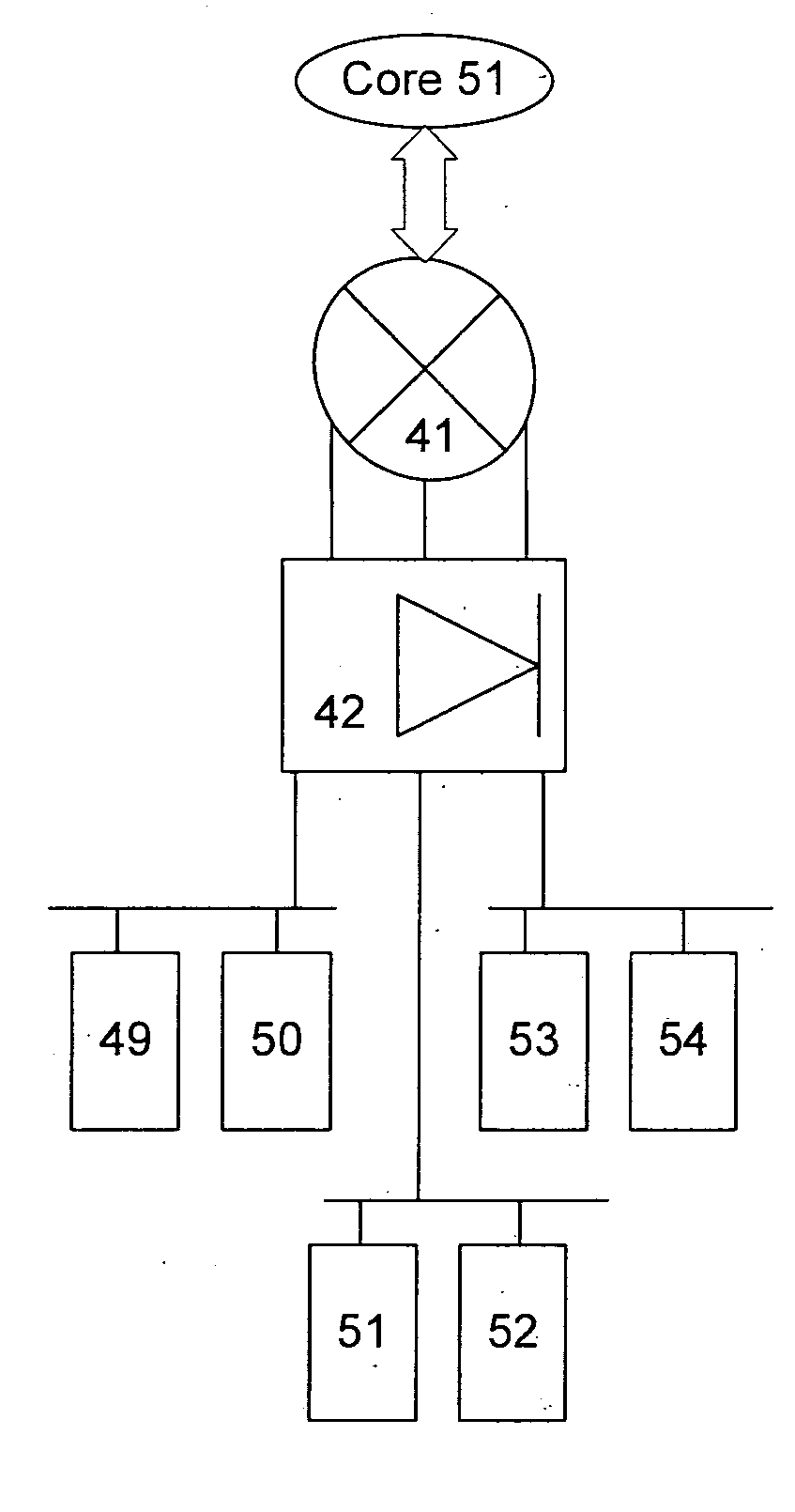
[0017] To overcome the disadvantages of prior art data center topology, a topology in accordance with the present invention efficiently routes traffic between internal sub-nets as well as traffic destined to or arriving from an outside network. The data center topology employs transparent layer 7 and layer 4 services on a co...


PUM


Abstract

A data center topology routes traffic between internal sub-nets and between a sub-net and an outside network through a common chain of services. The data center topology employs transparent layer 7 and layer 4 services on a common chassis or platform to provide routing, load balancing and firewall services while reducing the number of devices necessary to implement the data center and simplifying configuration.

Description

CROSS-REFERENCES TO RELATED APPLICATIONS [0001] This application claims priority from commonly assigned provisional patent application entitled “Data Center Network Design And Infrastructure Architecture” by Mauricio Arregoces and Maurizio Portolani, application No. 60 / 623,810, filed Oct. 28, 2004 the entire disclosure of which is herein incorporated by reference.BACKGROUND AND SUMMARY OF THE INVENTION [0002] Data centers are an integral element in supporting distributed client / server computing. Data centers enable the use of powerful applications for the exchange of information and transaction processing and are critical to the success of modem business. A typical n-tier data center uses multiple physical devices. These devices, shown in FIG. 1, may include a firewall 10 that provides access security for a server farm having web servers 11 and 12, a Layer 3 switch 13 that functions as a router and a content switch 14 to load balance traffic to web servers 11 and 12. Each of the web...

Claims


Application Information

Patent Timeline
IPC IPC(8): G06F15/16
CPCH04L63/0254H04L67/1002H04L67/1001
Inventor ARREGOCES, MAURICIOPORTOLANI, MAURIZIOMONCLUS, PEREKAHOL, ANURAGPULLELA, VENKATESHWAR RAORAJENDRAN, SARAVANAKUMARDEVIREDDY, DILEEP K.
Owner CISCO TECH INC
Why Eureka
Try Eureka