Measurement of coupled aerodynamic stability and damping derivatives in a wind tunnel

a technology of aerodynamic stability and derivatives, which is applied in the measurement of structures/machines, golf clubs, instruments, etc., can solve the problems of high cost, inability to provide the accuracy desired, and large size of models, and achieves low cost, high fidelity results, and minimize the impact of existing wind tunnel hardwar

Inactive Publication Date: 2006-05-11
BAE SYST INFORMATION & ELECTRONICS SYST INTERGRATION INC
View PDF9 Cites 14 Cited by
  • Summary
  • Abstract
  • Description
  • Claims
  • Application Information

AI Technical Summary

Benefits of technology

[0020] In summary, the proposed method and apparatus of the present invention provides a low cost alternative to current wind tunnel test techniques for the measurement of dynamic stability derivatives to include both damping terms and rotary derivatives. This invention is predicated upon existing demonstrated methods which yield high fidelity results. The invention minimizes impact to existing wind tunnel hardware and is easily implementable within current wind tunnel models. The method can be implemented in single, three, and six degrees of freedom, and the stability derivatives measured are precisely determined through usual analytical methods of data reduction. Thus, the present invention provides not only a reduced cost, but substantially improves the accuracy of the coefficients under evaluation and test results.

Problems solved by technology

However, this requires that an actual full size body be utilized, and if the tests prove unsatisfactory, require redesign and rebuilding of the actual full size body.
Likewise, these tests are expensive and do not provide the accuracy desired.
However this requires a full size model and expensive in flight tests.
Even though these devices may provide satisfactory inputs, they are relatively expensive to utilize and set up within restricted types of wind tunnels.
Furthermore, these experimental methods and wind tunnel testing only measure the six static force and moment derivatives.
Due to cost of the testing required to accurately capture the dynamic coefficients, inclusion in simulated wind tunnel tests is limited at best, and most times the coefficients utilized are calculated values of the derivatives and not measured results.
However, due to the extremely complex nature of the driving aerodynamic phenomena, calculated values often contain sufficient error to corrupt simulation tests.
Testing for these derivatives using current techniques is impractical due to the high cost.

Method used


Image

  • Measurement of coupled aerodynamic stability and damping derivatives in a wind tunnel
  • Measurement of coupled aerodynamic stability and damping derivatives in a wind tunnel
  • Measurement of coupled aerodynamic stability and damping derivatives in a wind tunnel

Examples


Embodiment Construction

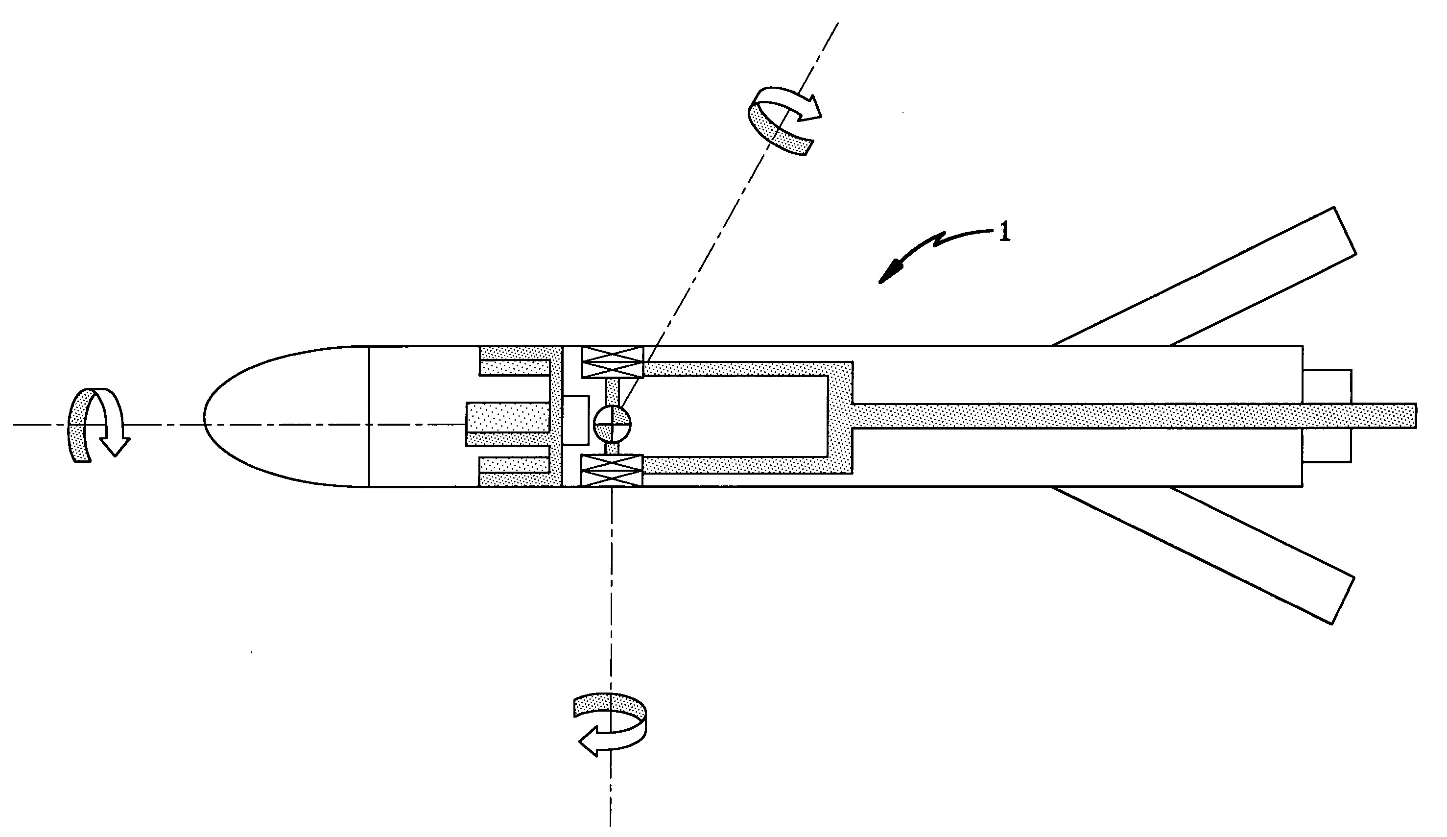
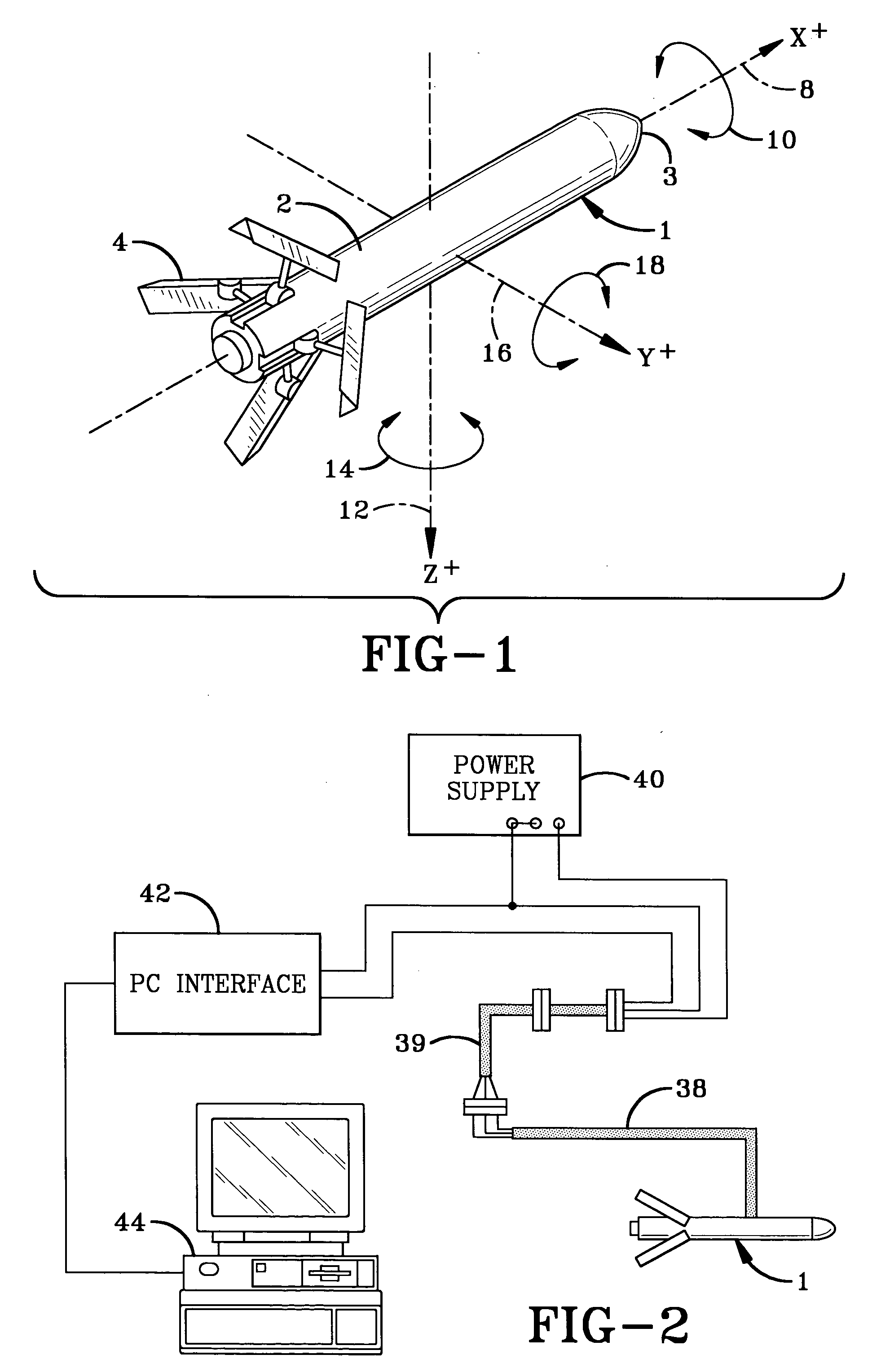
[0034]FIG. 1 is a diagrammatic perspective view of a model to be tested in a usual wind tunnel in accordance with the present invention. The model shown is a type of drogue or decoy indicated generally at 1, which is towed by a military aircraft, such as shown and described in U.S. Pat. No. 4,852,455. Model 1 consists of a generally cylindrical body 2 having a pointed nose 3 and a plurality of retractable and expandable fins 4. However, the concept and features of the present invention can be used for various types of free-fall bodies, projectile bodies, or self-powered bodies without departing from the concept of the invention, and need not be limited to such towed objects.

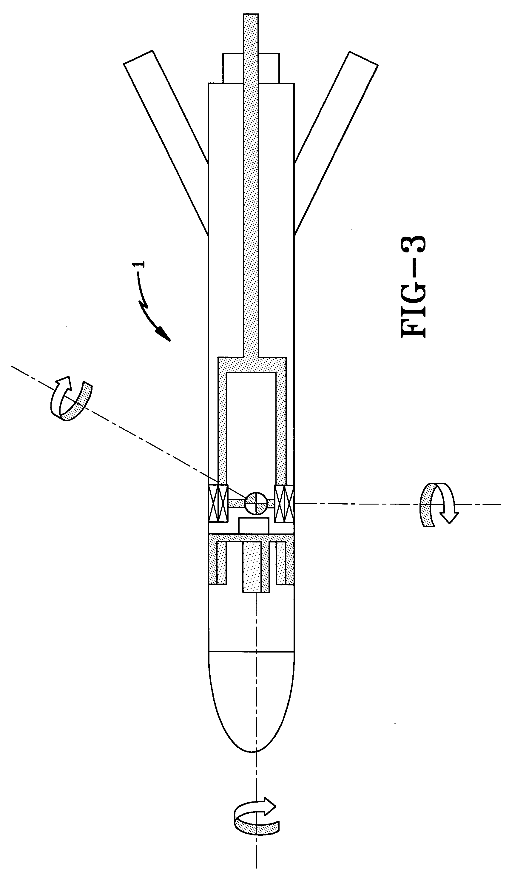
[0035] The details of the apparatus of the present invention, and in particular the miniature six degree of freedom package, is shown particularly in FIGS. 5-7 and is indicated generally at 6. The six forces acting on model 1 are shown particularly in FIG. 1 and includes an axial force 8 and a roll moment 10, wh...


PUM


Abstract

An apparatus for measuring coupled aerodynamic stability and damping derivatives of an object, such as a missile, towed decoy, etc. in a wind tunnel. The object is mounted on a bearing in the wind tunnel and contains an instrumentation package which provides a plurality of signals for determining coupled moment derivatives. The package includes three rate sensors, three accelerometers, and two thermal detectors for measuring the time rate of change of the full six degree of freedom state vector for aerodynamic derivatives.

Description

BACKGROUND OF THE INVENTION [0001] 1. Technical Field [0002] The invention relates to a low cost alternative to the measurement and evaluation of rotary and damping aerodynamic derivatives in a wind tunnel. More particularly, the invention relates to an approach which combines miniature inertial measurement technology with signal processing techniques to allow coupled derivatives and damping terms to be measured. This approach is adapted to existing oscillation techniques for simplifying the measurement approach in lieu of complex heretofore used forced oscillation flexure balances. Single degree of freedom, as well as three degree of freedom damping measurements can be made, and measurement of coupled force and moment coefficients also is possible by modification to the sting adaptor, allowing full advantage of the six degree of freedom capability of the measurement apparatus to be taken. [0003] 2. Background Information [0004] In the design of bodies which move through the air, va...

Claims


Application Information

Patent Timeline
Patent Type & Authority Applications(United States)
IPC IPC(8): G01P13/00
CPCG01M9/06G01M9/08
Inventor CARLSON, MARK A.
Owner BAE SYST INFORMATION & ELECTRONICS SYST INTERGRATION INC
Why Eureka
Try Eureka