
Eureka
For R&D, Eureka makes reading and utilizing patents & technical documents easy.
Eureka AIR
Designed for self-driven R&D workflows. Generate viable solutions, solve complex R&D challenges, empower your innovation with AI.

Eureka Materials
Designed for material experts only. Revolutionize your material R&D, from search, analyze, to developing new materials.

TechResearch
Generate reliable direction feasibility study reports for your R&D in just a few steps.

TechSeek
Discover and master advanced knowledge NOW. Basics, ideas, possibilities, all at once.

TechMind
As an expert in R&D Theories, TechMind can generates customized viable solutions instantly.

TechRisk
Analyze your overall solution with one click, know your potential R&D risks in advance.

TechMonitor
Get weekly tech updates, stay abreast of the latest tech innovations and key insights.
Apparatus and method for measuring thickness and profile of transparent thin film using white-light interferometer
- Summary
- Abstract
- Description
- Claims
- Application Information
AI Technical Summary
Benefits of technology
Problems solved by technology
Method used
Image

Examples
first embodiment
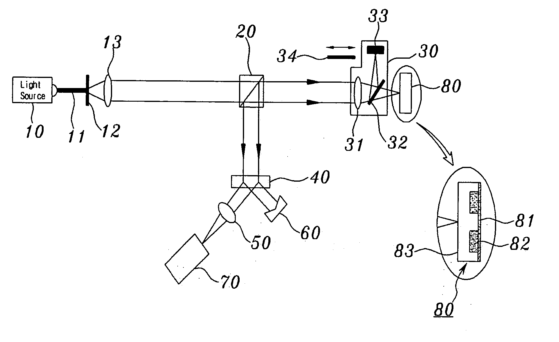
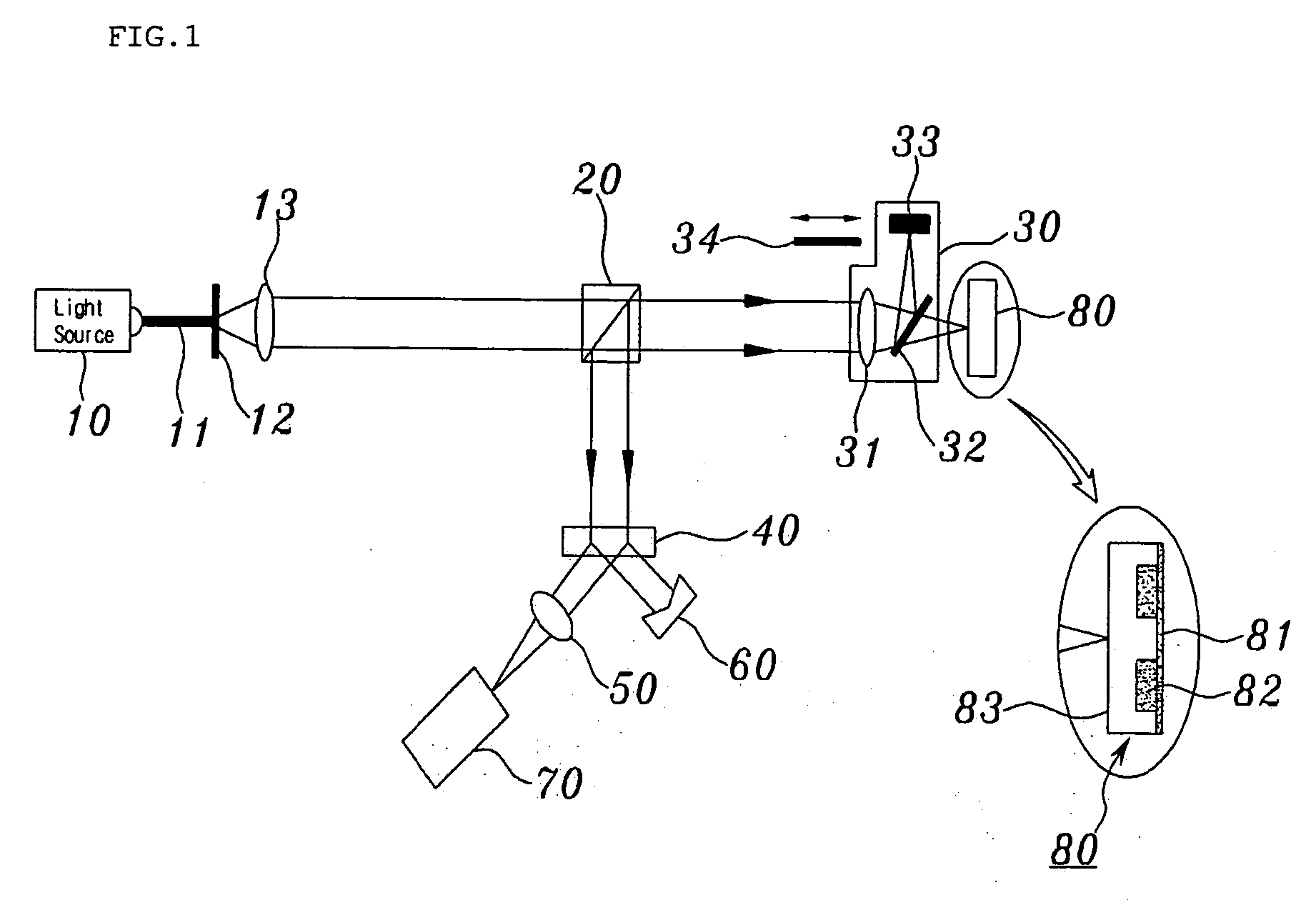
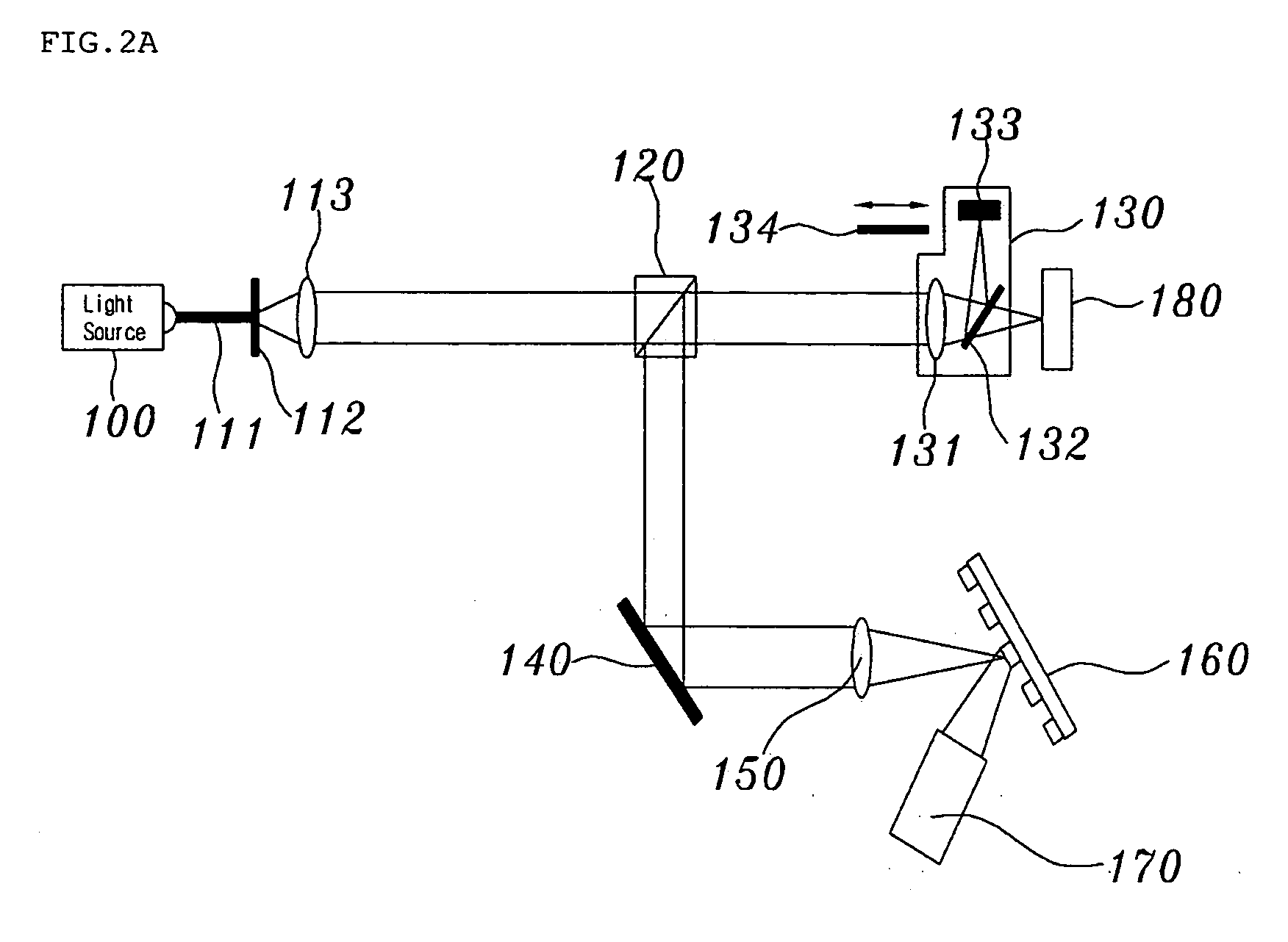
[0048]FIG. 2A is a diagram showing the construction of an apparatus for measuring the thickness and profile of a transparent thin film using a white-light interferometer according to the present invention, which illustrates an example of obtaining thickness information and profile information using a blocking surface that is included in a Michelson interferometer module.
[0049] The apparatus for measuring the thickness and profile of a transparent thin film using the white-light interferometer of FIG. 2A has a structure of obtaining information about a measurement region in real time, using a Michelson interferometer module 130 including therein a blocking surface, a condensing lens, and a diffraction grating. Such a structure can independently measure the thickness and the profile of the thin film by turning on or off the blocking surface.
[0050] The apparatus of FIG. 2A can separate and independently measure thickness information and profile information using the interference of mo...
second embodiment
[0058]FIG. 2B is a diagram showing the construction of an apparatus for measuring the thickness and profile of a transparent thin film using a white-light interferometer according to the present invention. In this case, thin film thickness information and thin film profile information are directly separated using the polarization of light, and are measured in real time.
[0059] In FIG. 2B, white light emitted from a light source 211 is converted into parallel light while passing through a collimating lens 212, and is then incident on a polarization device 213. The polarization device 213 functions to cause the intensity of light incident on a reference surface and the intensity of light incident on a measurement surface to be similar to each other, and emits incident parallel light as arbitrarily polarized light. That is, the polarization device 213 adjusts the size of horizontally and vertically polarized light to the same. Horizontally polarized light 214 and vertically polarized li...
third embodiment
[0061]FIG. 3A is a diagram showing the construction of an apparatus for measuring the thickness and profile of a transparent thin film using a white-light interferometer according to the present invention.
[0062] The embodiment of FIG. 3A is an apparatus having the same construction as the first embodiment of FIG. 2A, but there is a difference in that a condensing lens is replaced with cylindrical lenses 331 and 350. The remaining components of FIG. 3A, indicated by the same reference numerals as those of FIG. 2A, perform the same functions, so detailed descriptions thereof are omitted. Referring to FIG. 3A, the cylindrical lenses 331 and 350 extend a measurement region from a single point to a single line.
PUM
 Abstract
Description
Claims
Application Information
 - R&D Engineer
- R&D Manager
- IP Professional
- Industry Leading Data Capabilities
- Powerful AI technology
- Patent DNA Extraction
Browse by: Latest US Patents, China's latest patents, Technical Efficacy Thesaurus, Application Domain, Technology Topic, Popular Technical Reports.
© 2024 PatSnap. All rights reserved.Legal|Privacy policy|Modern Slavery Act Transparency Statement|Sitemap|About US| Contact US: help@patsnap.com