Optically measuring electric field intensities

a technology of electric field intensities and optically measuring, which is applied in the direction of instruments, laser details, measurement devices, etc., can solve the problems of invasive use of eo field intensities in eo field measurements, increased measurement difficulty of accumulated phase retardation, and inability to meet the requirements of eo field intensities, etc., to achieve adequate sensitivity, increase the sensitivity of the probe to an electric field, and reduce the effect of linear dimensions

Active Publication Date: 2006-05-11
LUCENT TECH INC
View PDF6 Cites 7 Cited by
  • Summary
  • Abstract
  • Description
  • Claims
  • Application Information

AI Technical Summary

Benefits of technology

[0008] Various embodiments provide apparatus and methods for EO measurement of intensities of electric fields. The apparatus typically include a probe having an electro-optically responsive material. To increase the probe's sensitivity to an electric field, the probe incorporates an electro-optically responsive optical resonator in which the probing light makes multiple traverses of the resonator's cavity. The multiple traverses enable a phase retardation produced by an applied electric field to accumulate. For this reason, an electro-optically responsive optical resonator can provide adequate sensitivity and still have significantly smaller linear dimensions than a bulk EO crystal. The smaller linear dimensions enable the measurement of variations in an electric field with a higher spatial resolution than is available with measurement probes that use bulk EO crystals.

Problems solved by technology

While some materials have a large EO effect, such materials are not always desirable for use in EO probes for measuring intensities of electric fields.
The large low-frequency dielectric constant increases the interaction between such materials and samples thereby making their use in EO measurements of field intensities invasive.
Unfortunately, measuring the accumulated phase retardation is also more difficult when the probe is made with a material having a low or moderate EO effect.

Method used


Image

  • Optically measuring electric field intensities
  • Optically measuring electric field intensities
  • Optically measuring electric field intensities

Examples


Embodiment Construction

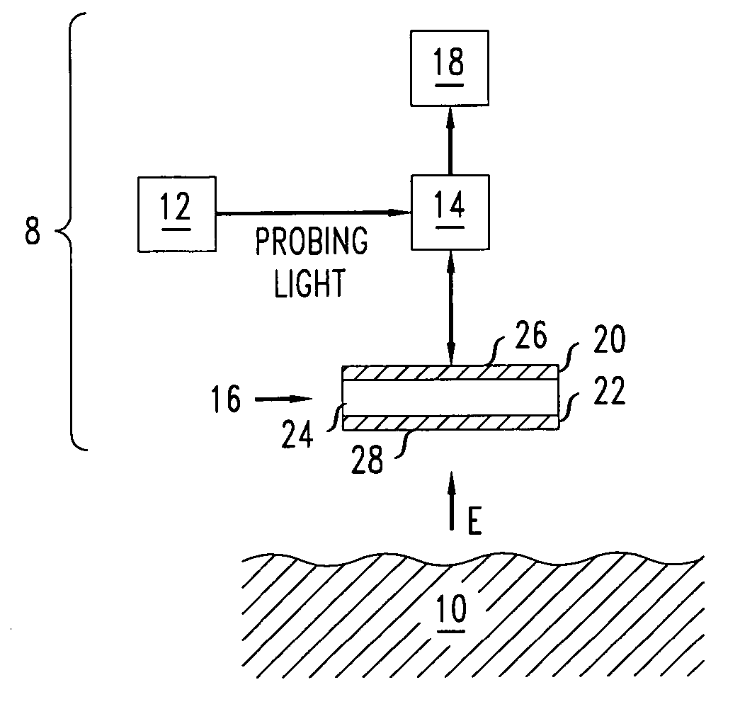
[0021]FIG. 1 shows an electro-optic (EO) apparatus 8 that is capable of measuring the intensity of a component of an electric field, E, with a high spatial resolution. Some embodiments of the EO apparatus 8 use infrared light to measure an intensity pattern of a component of an electric field to a vertical spatial resolution of about 5 micrometers (μ) or better and can produce a vertical spatial resolution of at least 2μ. With visible light, other embodiments may be able to produce even better spatial resolutions. Thus, some embodiments of the EO apparatus 8 are able to measure the intensities of components of electric fields at a distance of a few microns from the surface of an object 10. These embodiments of the EO apparatus 8 may be useful for tests of integrated circuits, which are based on mapping electric field patterns near said circuits.

[0022] The EO apparatus 8 includes a laser source 12, an optical beam splitter 14, an optical resonator 16, and an optical detector 18. The...


PUM


Abstract

An apparatus includes an optical resonator and a passive optical device. The optical resonator has first and second optical reflectors and an optical cavity interposed between the reflectors. The optical resonator includes an electro-optically responsive material. One of the reflectors is a distributed Bragg reflector. A passive optical device is configured to direct light through the first optical reflector. The optical resonator is configured to return a portion of the light through the first reflector.

Description

[0001] The U.S. Government has a paid-up license in this invention and the right in limited circumstances to require the patent owner to license others on reasonable terms as provided for by the terms of Contract No. HR0011-04-C-0048 awarded by DARPA Tactical Technology Office (TTO).BACKGROUND [0002] 1. Field of the Invention [0003] This invention relates generally to the measurement of electric fields and more specifically to the use of the electro-optic effect to measure intensities of such fields. [0004] 2. Discussion of the Related Art [0005] In various situations, it is desirable to measure the intensity of an electric field. One method for making such measurements involves using a bulk crystal having an electro-optic (EO) effect. In particular, a non-centrosymmetric crystal responds to an applied electric field via an EO effect. In the EO effect, application of an electric field changes a refractive index of a material. Due to the EO effect, light traveling through an electro-...

Claims


Application Information

Patent Timeline
Patent Type & Authority Applications(United States)
IPC IPC(8): H01S3/115
CPCG01R15/241
Inventor MITROFANOV, OLEG
Owner LUCENT TECH INC
Why Eureka
Try Eureka