

Optical module
a technology of optical modules and receptacles, applied in the field of receptacle-type ld modules, can solve the problems of no small receptacle-type module containing optical fibers, and achieve the effect of preventing backreflection and large siz
- Summary
- Abstract
- Description
- Claims
- Application Information
AI Technical Summary
Benefits of technology
Problems solved by technology
Method used
Image

Examples
first embodiment (
Combination of Faraday Rotator and Permanent Magnet)
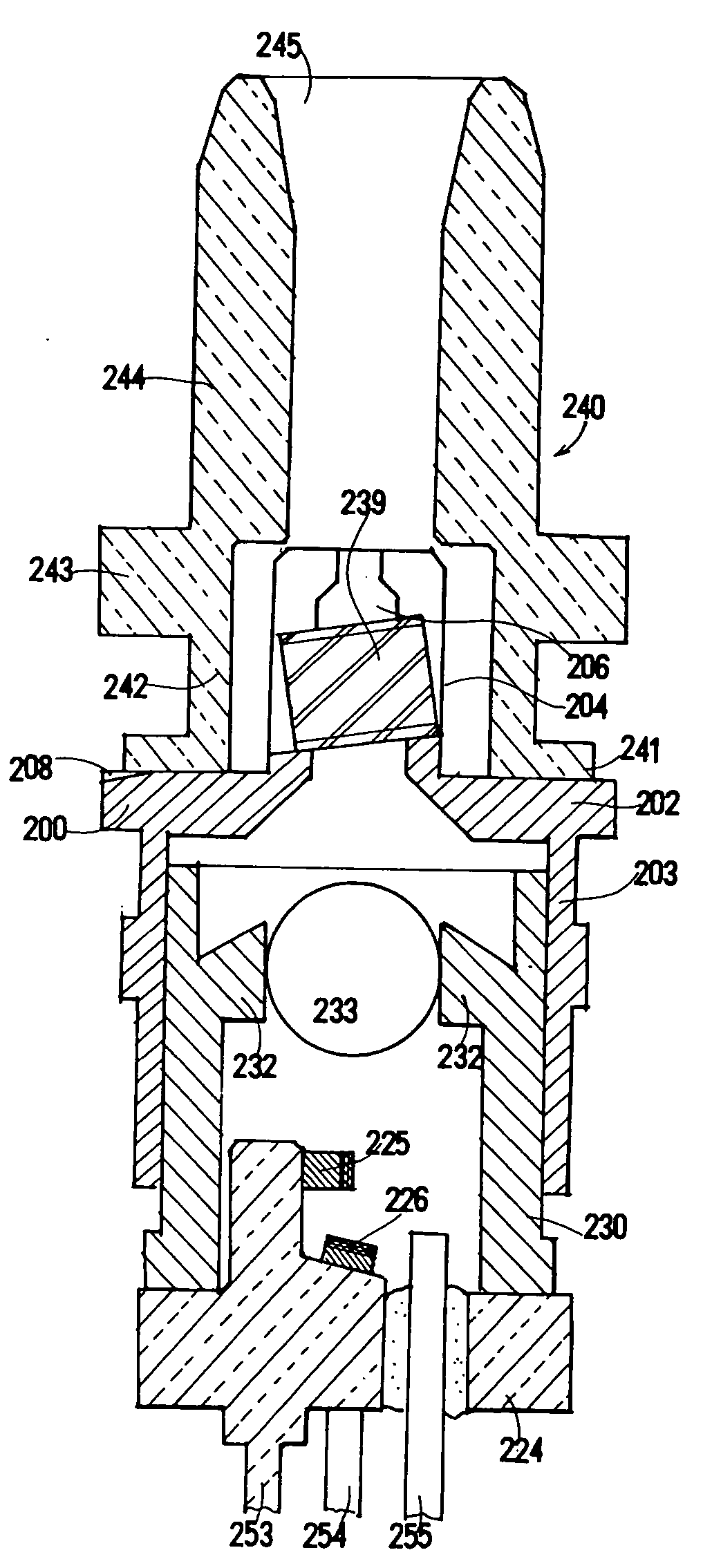
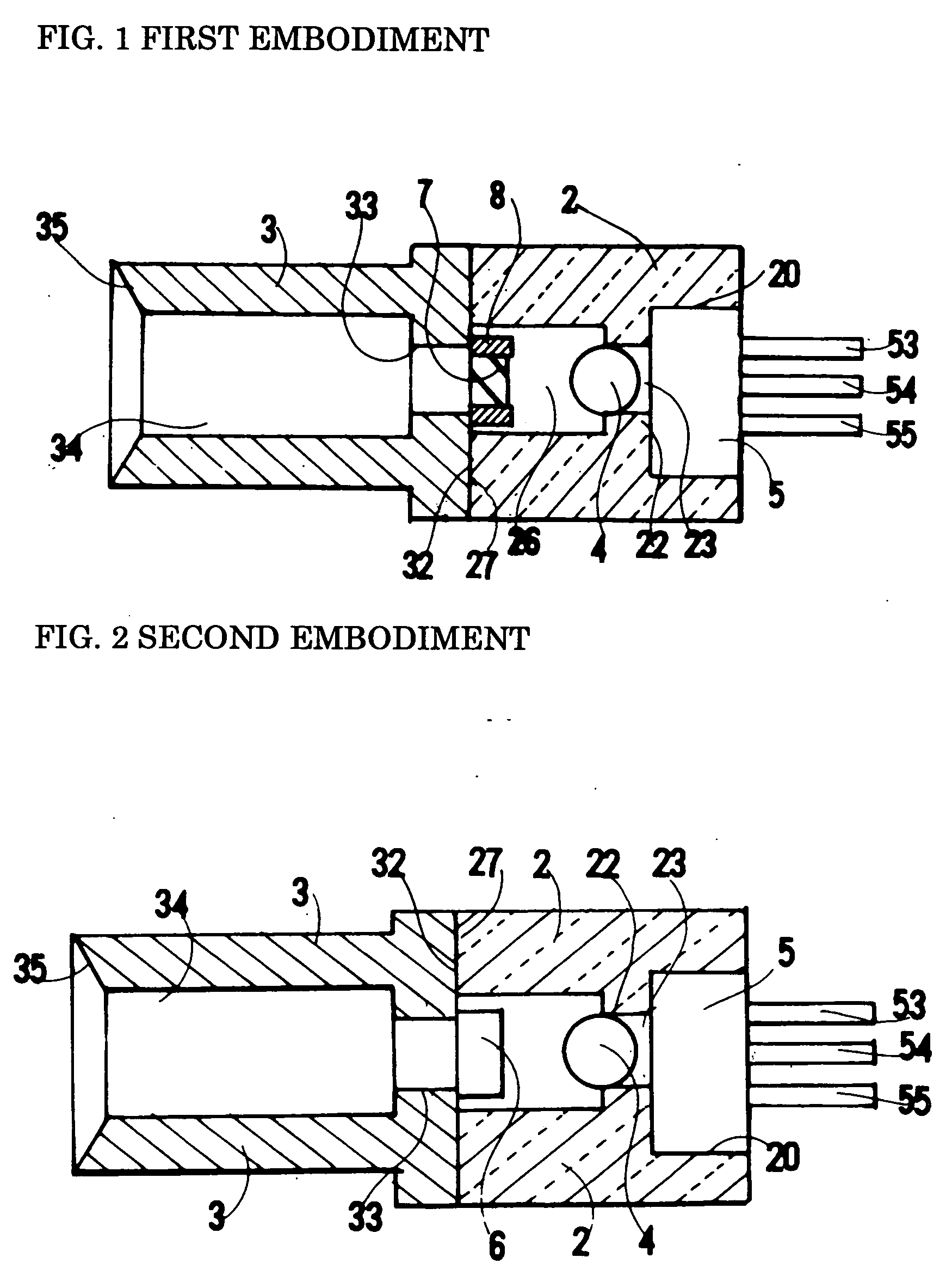
[0058] An optical module in a first embodiment of the present invention is described below by referring to FIG. 1. The optical module comprises a cylindrical holder 2, a cylindrical receptacle 3 adjacent to the holder 2, an optical device 5 housed in the holder 2, and a small Faraday rotator 7 fixed on the rear wall of the receptacle 3.
[0059] The optical device 5 is inserted into a optical-device-housing space 20 at the rear of the holder 2 and is fixed there. The holder 2 is provided with a lens-holding wall 22 at its middle portion. A through hole 23 passes through the wall 22 at its center. A spherical lens 4 is fixed at the front of the through hole 23. The front end of the holder 2 forms a smooth holder front face 27.
[0060] The receptacle 3 is provided at its rear with a wider receptacle rear face 32. The receptacle rear face 32 is welded with the holder front face 27 of the holder 2. The receptacle 3 is provided at its fron...
second embodiment (
Self-Magnetized-Type Faraday Rotator)
[0076] An optical module in a second embodiment of the present invention is described below by referring to FIG. 2. This optical module also has nearly the same structure as that in the first embodiment. The optical module comprises a cylindrical holder 2, a cylindrical receptacle 3 adjacent to the holder 2, an optical device 5 housed in the holder 2, and a small self-magnetized-type Faraday rotator 6 fixed on the rear wall of the receptacle 3. Whereas the first embodiment uses a combination of the permanent magnet 8 and the Faraday rotator 7, the combination is replaced with the self-magnetized-type Faraday rotator in this embodiment. The self-magnetized-type Faraday rotator is a device that can produce the Faraday rotation without the use of a permanent magnet. Because this device can eliminate the use of the permanent magnet, the number of parts can be decreased. It also produces a spatial margin.
[0077] The following explanation can be applie...
third embodiment (
Combination of Faraday Rotator, Permanent Magnet, and Sheet Polarizer)
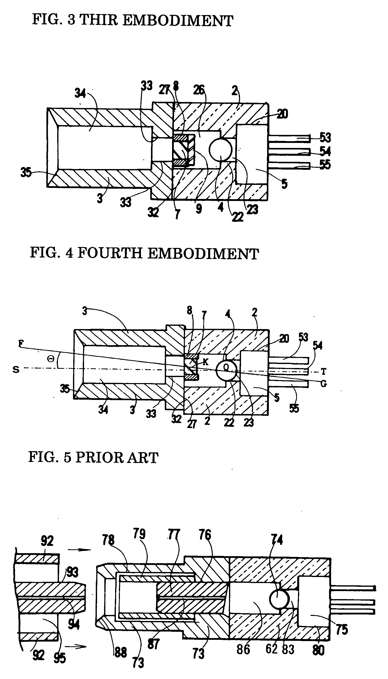
[0078] An optical module in a third embodiment of the present invention is described below by referring to FIG. 3. This optical module also has nearly the same structure as that in the first and second embodiments. The optical module comprises a cylindrical holder 2, a cylindrical receptacle 3 adjacent to the holder 2, an optical device 5 housed in the holder 2, and a combination of a Faraday rotator 7, a permanent magnet 8, and a sheet polarizer 9, which combination is fixed on the rear wall of the receptacle 3. The optical components are placed in the following order: the laser diode, sheet polarizer, Faraday rotator, and optical fiber.
[0079] Whereas the first embodiment uses a combination of the permanent magnet 8 and the Faraday rotator 7, the sheet polarizer 9 is added to the combination in this embodiment. The sheet polarizer 9 is a sheet that has a function of selectively transmitting only the light having...
PUM
 Abstract
Description
Claims
Application Information