Filter catalyst

a filter catalyst and catalyst technology, applied in the field of filter catalysts, can solve the problems of not purifying the gaseous component, the catalytic layer has a lower gas dispersibility property, and the exhaust gas pressure loss, etc., to promote decomposition, promote decomposition and purification of particulates, and shorten the time period

Active Publication Date: 2006-05-11
CATALER CORP
View PDF4 Cites 16 Cited by
  • Summary
  • Abstract
  • Description
  • Claims
  • Application Information

AI Technical Summary

Benefits of technology

[0041] Such construction can bring a following effect. That is, reacting heat generated when MC, CO and NOx are purified at the upstream first catalytic portion is transferred to the downstream second catalytic portion. The transferred heat promotes decomposition and purification of the particulates captur

Problems solved by technology

If the ventilation holes sufficiently allowing the exhaust gas to pass through was not formed in the filter catalyst, the captured particulates deposit on the catalyst-supporting substrate to cause a pressure loss of the exhaust gas.
However, due to small particle diameter of the heat-resistant inorganic oxide, there wa

Method used


Image

  • Filter catalyst
  • Filter catalyst
  • Filter catalyst

Examples


example 1

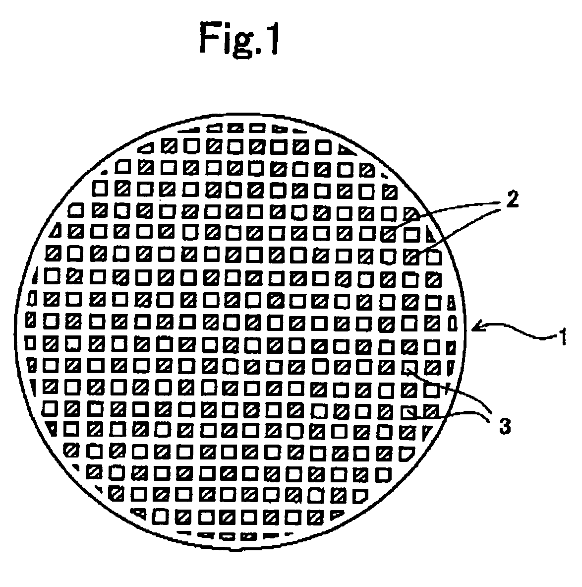
[0050] Firstly, a slurry A to be coated on a catalyst-supporting substrate 1 shown in FIG. 1 was prepared. FIG. 1 is an upper end surface of a catalyst-supporting substrate 1. When preparing the slurry A, alumina (Al2O3) powder was put into a deionized water, and a solution was stirred so that the alumina powder was dispersed into the deionized water. Then, by subjecting the solution to a milling operation, the slurry A was prepared. The alumina dispersed into the slurry A has an average particle diameter of 0.8 μm.

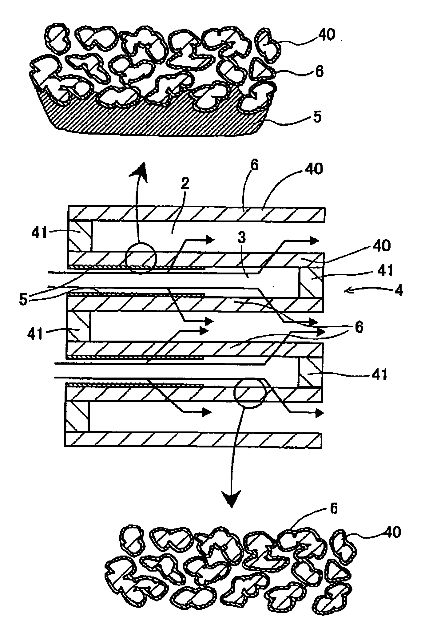
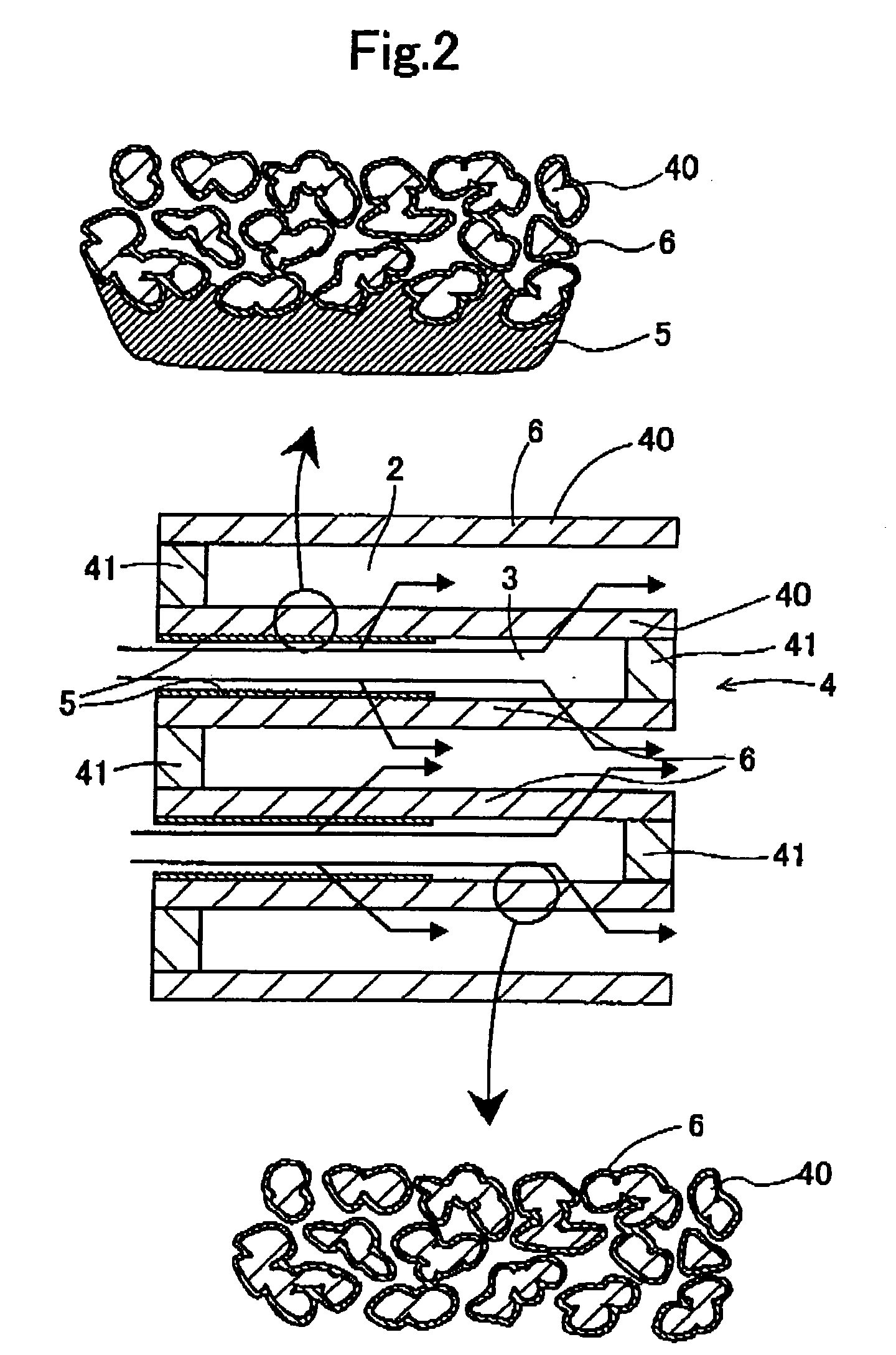
[0051] Then, the prepared slurry A was coated on the catalyst-supporting substrate 1, as shown in FIGS. 1 and 2. FIG. 2 is an axial cross-sectional view of a filter catalyst 4. The honeycomb-shaped catalyst-supporting substrate 1 made of a cordierite has substantially circular tubular shape as a whole, and has an outer diameter of 129 mm, an axial length of 150 mm and 2 liters apparent volume, respectively. The catalyst-supporting substrate 1 has plural cells 2 and plura...

example 2

[0062] The slurry A was prepared and was coated on the catalyst-supporting substrate in the same manner as the Example 1, to form the second loading layer. The slurry A was coated on the whole catalyst-supporting substrate. After drying of the slurry A, the catalyst-supporting substrate was weighed. As a result, loading of the alumina by loading amount of 100 g per the 1 liter apparent volume of the catalyst-supporting substrate was confirmed. Also confirmed was that the alumina loading layer produced by the slurry A was formed on the inside surface of the pores of the cellular wall in substantially uniform thickness, similar to the second catalytic portion of the Example 1.

[0063] Then, the slurry 8 was prepared and coated on the catalyst-supporting substrate in the same manner as the Example 1, to form the first loading layer. The slurry B was coated on the surface of the cellular wall, in an area spreading from the upstream end to a 50 mm point away from the upstream end. The ope...

example 3

[0068] The slurry A was prepared in the same manner as the Example 1, and was coated on the catalyst-supporting substrate in the area spreading from the downstream end to a 75 mm point away from the downstream end, to form the second loading layer. After drying of the slurry A, the catalyst-supporting substrate was weighed. As a result, loading of the alumina by loading amount of 75 g per the 1 liter apparent volume of the catalyst-supporting substrate was confirmed. Also confirmed was that the alumina loading layer produced by the slurry A was formed on the inside surface of the pores of the cellular wall in substantially uniform thickness, similar to the second catalytic portion of the Example 1.

[0069] Then, the slurry B was prepared and coated on the catalyst-supporting substrate in the same manner as the Example 1, to form the first loading layer. The slurry B was coated on the surface in the area spreading from the upstream end to a 75 mm point away from the upstream end of th...


PUM

PropertyMeasurementUnit
Particle diameteraaaaaaaaaa
Temperatureaaaaaaaaaa

Abstract

A filter catalyst of the present invention is comprised of a catalyst-supporting substrate 1, and catalytic portions 5, 6 for purifying an exhaust gas. The catalytic portions includes the first catalytic portion 5 for purifying SC, CO and NOx, and the second catalytic portion 6 for purifying the particulates. The first catalytic portion 5 is formed on a surface of at least a portion of the cellular wall 40, and the second catalytic portion 6 is formed on an inside surface of the pores. In the filter catalyst of the present invention purifying ability of the exhaust gas is increased, and the filter catalyst of the present invention can suppress rise of the pressure loss of the exhaust gas.

Description

BACKGROUND OF THE INVENTION [0001] 1. Field of the Invention [0002] The present invention relates to a filter catalyst which removes particulates contained in an exhaust gas exhausted from an internal-combustion engine such as a diesel engine, and which purifies HC, CO, NOx simultaneously. [0003] 2. Description of the Related Art [0004] In the exhaust gas exhausted from the internal-combustion engine such as the diesel engine etc., components such as HC, CO, NOx etc. as well as particulates are contained. The particulates contain substance which is harmful to a human body and which requires to be removed from environmental aspect. [0005] For purification of such exhaust gas, a filter catalyst which is sometimes called as diesel particulate filter (DPF) were used. The filter catalysts are set forth in Japanese Unexamined Patent Publication (KOKAI) No. 9-173,866 and Japanese Unexamined Patent Publication (KOKAI) No. 2002-295,228. In conventional filter catalysts, a catalytic layer was...

Claims


Application Information

Patent Timeline
IPC IPC(8): B01J21/04
CPCB01J23/42B01J35/0006B01J35/023B01J37/0242B01J37/0244F01N3/0222F01N3/0231F01N3/035F01N2570/10F01N2570/12F01N2570/14B01D53/945B01D53/9472B01D2255/1021B01D2255/9155Y02T10/22Y02A50/20Y02T10/12
Inventor TSUJI, MAKOTOAONO, NORIHIKOOKI, DAISUKE
Owner CATALER CORP
Why Eureka
Try Eureka