Distributed control system

a control system and distribution control technology, applied in the direction of program control, multi-programming arrangements, program control, etc., can solve the problems of inability to ensure the fast response time of all accesses, system cost increase is inevitable, and inability to perform well load sharing, etc., to facilitate the sharing process, minimize the redundancy of the circuit, and enhance the effect of fault toleran

Inactive Publication Date: 2006-05-11
HITACHI LTD
View PDF5 Cites 119 Cited by
  • Summary
  • Abstract
  • Description
  • Claims
  • Application Information

AI Technical Summary

Benefits of technology

[0010] In a distributed control system where a plurality of control units are connected via a network, a first challenge of the present invention is to provide a load sharing method allowing for efficient operation of each control unit, while ensuring the performance of real-time processing.
[0013] Moreover, a third challenge is to virtualize a plurality of control circuits and facilitate a sharing process. In other words, this is to realize system uniformity in view from a user program, thus eliminating the need to program caring about a combination of a particular control circuit and a particular sensor or actuator, so that the system can be treated as if it was a single high-performance control circuit.
[0014] A fourth challenge of the present invention is to minimize the circuit redundancy and accomplish enhanced fault tolerance and a simple sharing process, applicable to cost-sensitive systems like motor vehicles.
[0015] To achieve the foregoing first challenge, the present invention provides a distributed control system where a plurality of control units connected via a network execute a plurality of tasks, and each control unit is arranged such that information of a deadline or task run cycle period as time required until task completion is given for each task and a control unit on which a task will be executed is selected according to the deadline or task cycle period. Each control unit is arranged such that time required to complete task processing and sending and return communication latency information if a task is executed on another control unit other than the control unit where the task was invoked to run are given for each task, thereby allowing for determining per task whether real-time processing can be ensured when the task is executed on another control unit connected via the network and selecting a control unit on which the task should be executed.
[0021] Furthermore, the third challenge is solved such that task sharing is implemented by OS or middleware and a user program does not care that a particular task is executed exclusively by a particular control unit, and profit can be taken from the sharing process with simple user programming.

Problems solved by technology

If local tasks are not processed by load sharing, as suggested in patent document 3, few tasks remain to be processed by load sharing and, consequently, load sharing cannot be performed well.
A conceivable solution is duplicating all control units, but system cost increase is inevitable.
However, in a situation where a great number of control circuits, sensors, and actuators send and receive information simultaneously, it is hard to ensure fast response time for all accesses.

Method used


Image

  • Distributed control system
  • Distributed control system
  • Distributed control system

Examples


embodiment 1

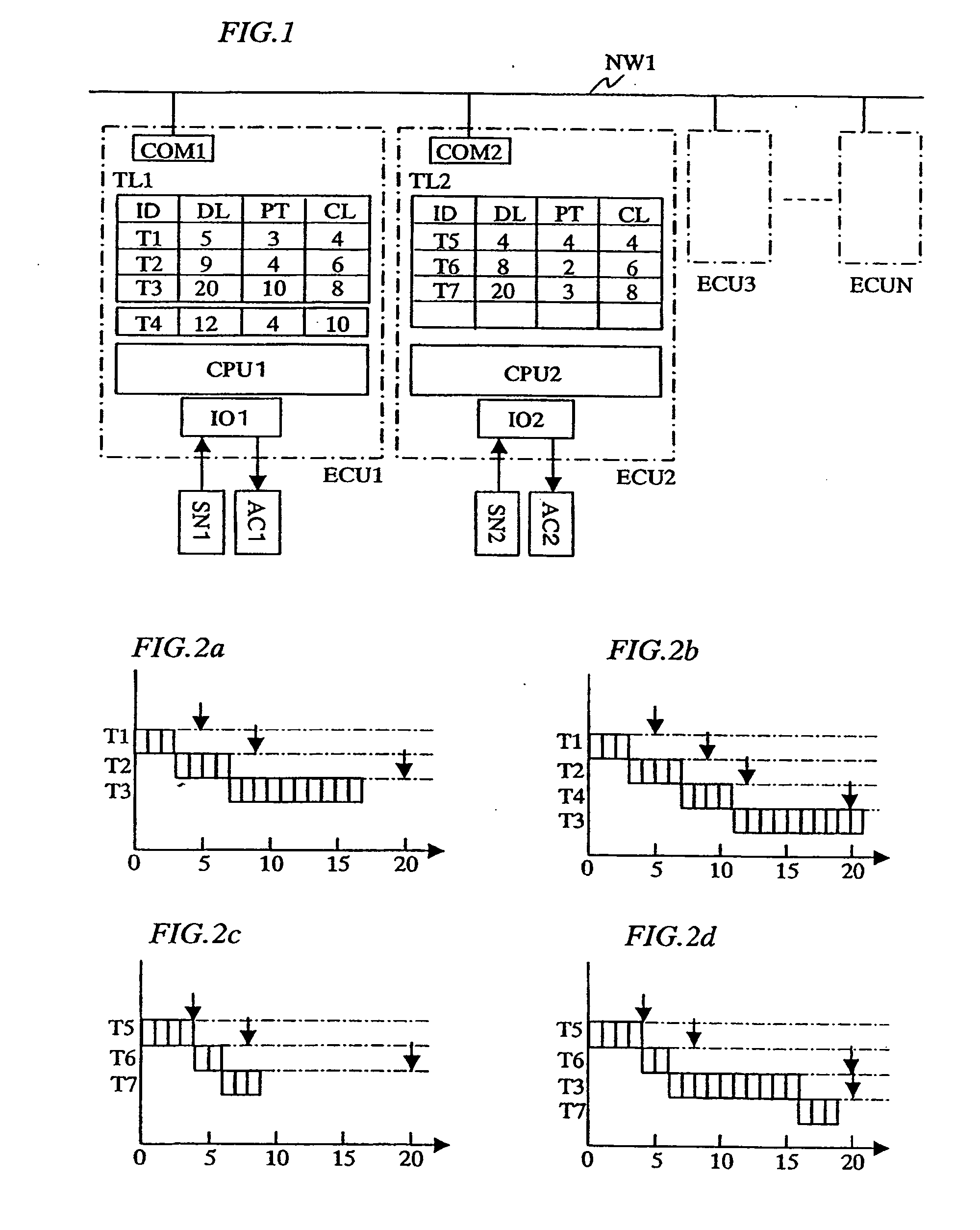
[0042] Embodiment 1 of the present invention is described with FIGS. 1 and 2. FIG. 1 shows a system schematic diagram where N control units ECU1 to ECUN are connected to a network NW1. However, control units ECU1 to ECU3 only are shown in FIG. 1; other control units are omitted. Internal structures of control units ECU1 and ECU 2 only are shown, as they are necessary for explanation. A control unit ECU1 is internally comprised of a communication device COM1 which is responsible for data communication, connecting to the network NW1, a control circuit CPU1 which processes tasks, and an input-output control circuit IO1 which sends and receives signals to / from a suite of sensors SN1 and a suite of actuators AC1. A task management list TL1 is also shown. The task management list TL1 is a list for managing tasks requested to run and waiting for being executed. This list is stored on a storage area and under the management of, e.g., an operating system run. The control units ECUs are so-ca...

embodiment 2

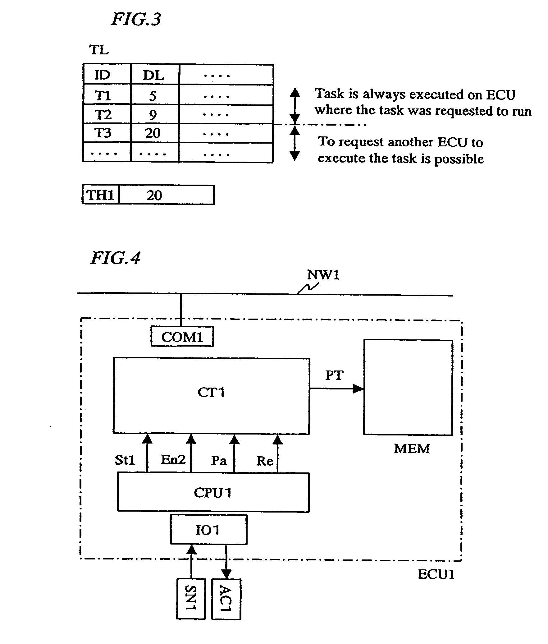
[0051]FIG. 3 shows a task management list provided to explain another embodiment of load sharing in order that each control unit processes tasks in a deadline-compliant schedule. Embodiment 2 uses the deadline only in determining a task that should be requested of and processed by another control unit. As compared with Embodiment 1, such decision is made in a simple way in this example of load sharing. In the task management list TL on each control unit, necessary information per task ID is managed in the same manner as described for FIG. 1. However, in this embodiment, it is sufficient to manage only the deadline DL information for each task and, thus, the list shown in FIG. 3 includes the deadline DL values sorted in ascending order. Besides, a threshold time TH1 of deadline DL is set separately. The threshold time is stored in a storage area of a memory, register, and the like.

[0052] In Embodiment 2, each control unit executes a task whose deadline is less than the threshold tim...

embodiment 3

[0055]FIG. 4 shows a control unit schematic diagram where task processing time PL registered in the task management list TL on each control unit is updated by past statistical data. The task processing time PT can be considered from a perspective as follows: a task execution flow is predicted and the processing time corresponds to the number of cycles of executive instructions to execute the flow. However, as mentioned in the description of Embodiment 2, the task processing time is difficult to estimate exactly, because it changes, according to circumstances. Thus, in Embodiment 3, means for measuring task processing time CT1 is provided to measure time in which a task is completed. According to actual measurements, the processing time value is updated.

[0056] When a task start indicating signal St1 is input to the means for measuring task processing time CT1, an internal counter (not shown) of the means for measuring task processing time CT1 starts to count. When a task end indicat...


PUM


Abstract

In a distributed control system where a plurality of control units are connected via a network, the invention allows for efficient operation of each control unit, while ensuring real-time processing. To provide a distributed control system in which ensured real-time processing and enhanced fault tolerance are achieved, information of a deadline or task run cycle period as time required until task completion is given for each task and a control unit on which a task will be executed is selected according to the deadline or task cycle period. A first control circuit and related sensors and actuators are connected by a dedicated path on which fast response time is easy to ensure and another control circuit and related sensors and actuators are connected via a network. When the first control circuit operates normally with sufficient throughput, the first control circuit is used for control; in case the first control circuit fails or if its throughput is insufficient, another control circuit is used.

Description

CLAIM OF PRIORITY [0001] The present application claims priority from Japanese application JP 2004-324679 filed on Nov. 9, 2004, the content of which is hereby incorporated by reference into this application. FIELD OF THE INVENTION [0002] The present invention relates to a distributed control system where a plurality of control units which execute a program for controlling a plurality of devices to be controlled are connected via a network and, in particular, to a distributed control system for application strictly requiring real-time processing, especially typified by vehicle control. BACKGROUND OF THE INVENTION [0003] In electronic control units (ECUs) for motor vehicles or the like, a control circuit (CPU) generates a control signal, based on information input from sensors and the like and outputs the control signal to actuators and the actuators operate, based on the control signal. Lately, such electronic control units have been used increasingly in motor vehicles. The control ...

Claims


Application Information

Patent Timeline
Patent Type & Authority Applications(United States)
IPC IPC(8): G06F9/46
CPCG05B19/0421G05B2219/25229G05B2219/25231
Inventor KATO, NAOKIARAKAWA, FUMIO
Owner HITACHI LTD
Why Eureka
Try Eureka