Substrate rotation type treatment apparatus

a treatment apparatus and substrate technology, applied in the direction of photomechanical equipment, cleaning using liquids, instruments, etc., can solve the problems of mixing substances, hydrophilic material thin film coming off the inside wall surface, etc., and achieve the effect of removing the causes of substrate contamination

Active Publication Date: 2006-05-18
DAINIPPON SCREEN MTG CO LTD
View PDF0 Cites 22 Cited by
  • Summary
  • Abstract
  • Description
  • Claims
  • Application Information

AI Technical Summary

Benefits of technology

[0023] In the substrate rotation type treatment apparatus of the invention according to claim 3 or 5, as compared with a cup in which an overall portion of the inside wall surface of a cup on which a treatment liquid having been diffused from the surface to the surroundings impinges is a hydrophobic surface, splashing of a hydrophilic treatment liquid is decreased, as well as a treatment liquid having impinged on the hydrophobic surface to be diffused on the surface rapidly flows to the adjacent hydrophilic surface to aggregate on the hydrophilic surface, so that splashing of a treatment liquid is unlikely to occur. Originally splashing of the treatment liquid impinged on the hydrophobic surface does not easily take place in itself. Thus, it is prevented that a treatment liquid having been diffused from the surface to impinge on the inside wall surface of a cup is splashed on the inside wall surface, and that a part of the used treatment liquid adheres to a surface of the substrate. On the other hand, when a treatment liquid having impinged on a hydrophilic surface to spread forming a thin film, or having flowed from a hydrophobic surface to a hydrophilic surface to aggregate, grows up to a certain size of droplets, it flows down from the hydrophilic surface to the adjacent hydrophobic surface, so that a time period of a treatment liquid being retained on the hydrophilic surfaces comes to be shorter. Consequently, it is prevented that a treatment liquid adheres to the inside wall surface of a cup to be dried, and that impurities or treatment liquid constituents are accumulated on the inside wall surface of the cup.
[0024] As described above, with the use of a substrate rotation type treatment apparatus according to claim 3 or claim 5, it is prevented that a treatment liquid having been diffused from the surface of a rotating substrate is splashed on the inside wall surface of a cup, as well as that a treatment liquid adheres to the inside wall surface of the cup to be dried, and that impurities or treatment liquid constituents are accumulated on the cup inside wall surface. As a result, it is possible to eliminate the causes of substrate contamination resulted from the cup.

Problems solved by technology

At this time, a problem arises in that when a treatment liquid such as used cleaning fluid contains impurities, the impurities in the treatment liquid becomes particles to be contamination-causing substances of a substrate W. Moreover, a further problem arises in that when a treatment liquid adheres to the inside wall surface of the cup 3 to be dried, and treatment liquid constituents are accumulated during the treatment of a number of substrates, the accumulated constituents become particles to adhere to the surface of a substrate W along with the treatment liquid having been splashed on the inside wall surface to be contamination-causing substances.
However, in a cup which material properties itself is improved to be hydrophilic by mixing a substance into resin material, a problem still exists in that the mixed substances will be eluted in the use of a long time period to become contamination-causing substances of a substrate.
Moreover, in a cup on the inside wall surface of which a hydrophilic material is deposited forming a thin film, a problem exists in that the thin film of hydrophilic material comes off from the inside wall surface in the use of a long time period to become contamination-causing substances of a substrate.

Method used


Image

  • Substrate rotation type treatment apparatus
  • Substrate rotation type treatment apparatus
  • Substrate rotation type treatment apparatus

Examples


Embodiment Construction

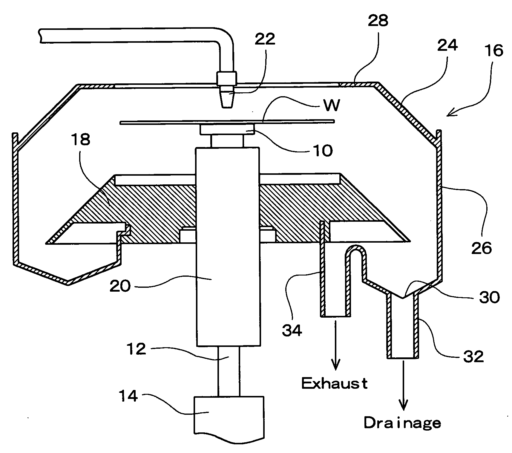
[0031] Several preferred embodiments according to the present invention are hereinafter described referring to FIG. 1.

[0032]FIG. 1 shows one example of preferred embodiments according to the invention, and is a longitudinal section showing a schematic construction of an essential part of a substrate rotation type treatment apparatus, for example, a substrate rotary cleaning apparatus (spin scrubber).

[0033] This cleaning apparatus includes a spin chuck 10 that holds a substrate W such as semiconductor wafers in a horizontal posture. The substrate W, which is held by the spin chuck 10, is made to rotate in a horizontal plane about a vertical axis by a spin motor 14 that is connected to a rotary shaft 12 supporting the spin chuck 10. There is provided around the substrate W a cup 16 that is formed in a container shape which top is open, and which surrounds the sides and the under side of the substrate W held by the spin chuck 10. There is provided a baffle member 18 of a truncated co...


PUM


Abstract

An apparatus causes a substrate to rotate and supplies a treatment liquid to a substrate surface to make a treatment, without concern that a mixed substance is eluted from a cup in the use for a long time, or a thin film comes off from an inside wall surface to be contamination-causing substances even if the cup made of a water-repellent material for collecting a treatment liquid becomes hydrophilic. A cup 16 disposed to surround the sides and underside of a substrate W rotating while being held by a spin chuck 10, and serving to collect a treatment liquid diffused from the substrate to the surroundings, is made of a plastic material. Further, an inside wall surface of an upper-side cup part 24 of the cup 16, being a portion on which the treatment liquid having been diffused from the substrate impinges, is roughened to be a hydrophilic surface.

Description

BACKGROUND OF THE INVENTION [0001] 1. Field of the Invention [0002] The present invention relates to a substrate rotation type treatment apparatus that holds substrates such as semiconductor wafers, liquid crystal display glass substrates, photo-mask glass substrates, optical disk substrates in a horizontal posture to cause the substrates to rotate about a vertical axis, and supplies to the substrate surface treatment liquids such as cleaning fluids, coating solutions, and developers to make the substrate treatment such as cleaning, coating, and development. [0003] 2. Description of the Related Art [0004] When substrates such as semiconductor wafers are held in a horizontal posture with a spin chuck to be brought in rotation about a vertical axis, and a treatment liquid, for example, a cleaning fluid, e.g., pure water is supplied to the substrate surface to make the cleaning treatment of the substrates, the cleaning fluid having been supplied on the substrate surface spreads to the ...

Claims


Application Information

Patent Timeline
Patent Type & Authority Applications(United States)
IPC IPC(8): B05C13/00B05C13/02B05C11/02
CPCG03F7/162G03F7/3021H01L21/67051
Inventor TOKURI, KENTAROMORINISHI, KENYAIWAMI, MASAKI
Owner DAINIPPON SCREEN MTG CO LTD
Why Eureka
Try Eureka