

Engine measuring equipment
- Summary
- Abstract
- Description
- Claims
- Application Information
AI Technical Summary
Benefits of technology
Problems solved by technology
Method used
Image

Examples
embodiments
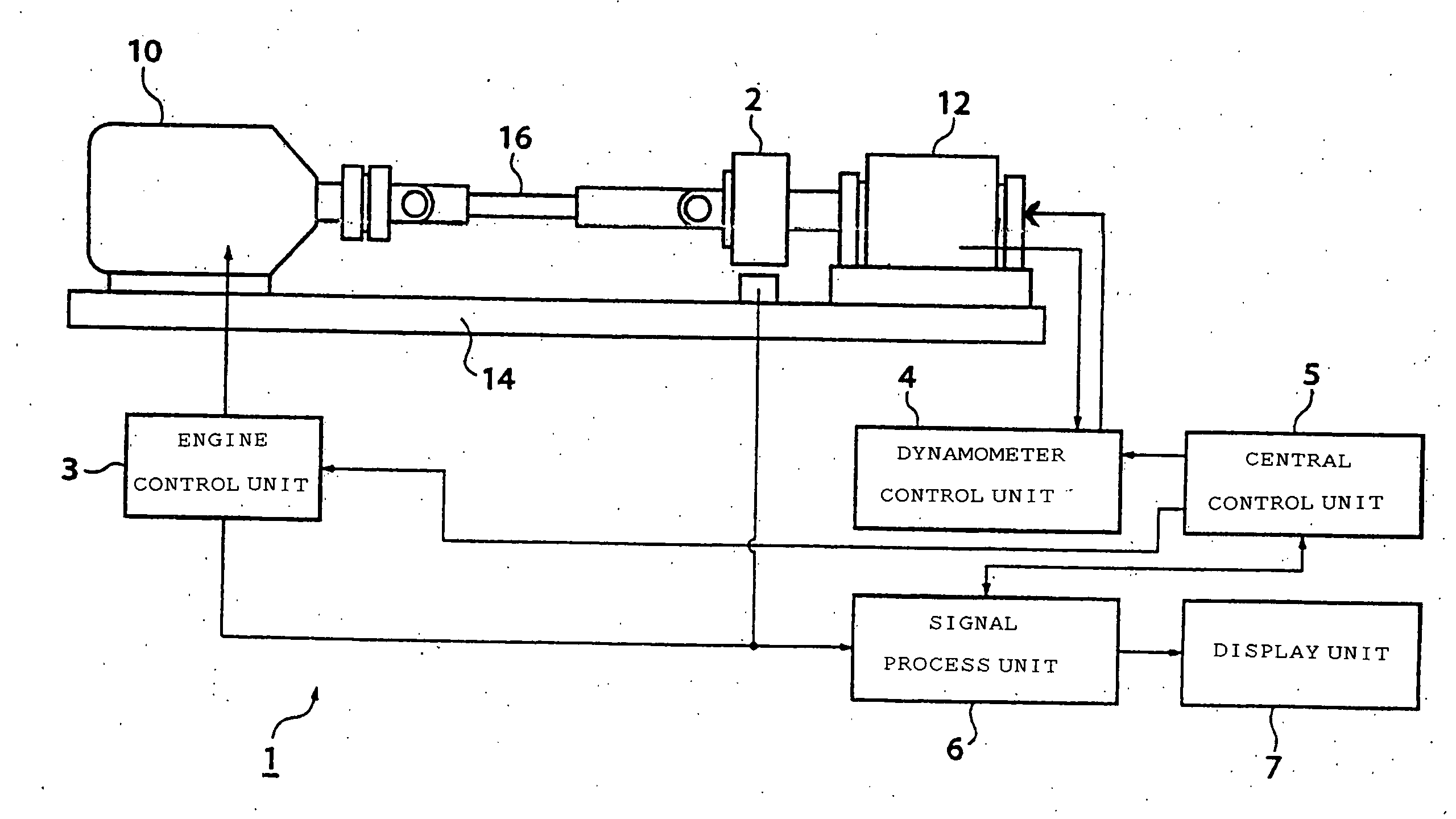
[0064] The holistic operation of engine measuring equipment 1 will be described as follows with reference to the flow chart of FIG. 3. An object of engine measuring equipment 1 of the present embodiment is to obtain the relationship between the engine torque Te and the revolution N for each throttle opening degree S, which is regarded most basic and important among indexes for assessing performance of an engine 10 being a test object.
[0065] At first, the engine measuring equipment 1 sets test conditions (S110). The test conditions for the present embodiment should include application of current and voltage from the dynamometer control portion 4 to the dynamometer 12 so as to provide load torque of the dynamometer 12 in stepwise waveform of approximately 5 Nm unit in series from 5 Nm to 70 Nm. The lasting period of a single step should be approximately 20 seconds. The stepwise waveform, which may be arranged upward or downward, had better be arranged upward in order to shorten the t...
PUM
 Abstract
Description
Claims
Application Information