Process for producing tubular ring with beads and die for use therein

a technology of tubular rings and beads, which is applied in the direction of manufacturing tools, forging/pressing/hammering apparatuses, forging presses, etc., can solve the problems of insufficient product dimensional accuracy and inability to increase productivity, and achieve the effect of more uniform molding

Inactive Publication Date: 2006-05-25
BRIDTONE 50
View PDF14 Cites 18 Cited by
  • Summary
  • Abstract
  • Description
  • Claims
  • Application Information

AI Technical Summary

Benefits of technology

[0034] Preferably, the base ring is in contact with the molding face of the metal mold at the central position of the molding face of the metal mold in the axial direction before electromagnetic forming. That is to say, in flaring, the internal diameter at the central position of the molding face of the metal mold in the axial direction is the smallest, and the outer circumference of the base ring is in contact with the molding face of the metal mold at the corresponding position. With this structure, the base ring is positioned at the corresponding position at molding, and thus more uniform molding can be performed. On the contrary, in nosing, the external diameter at the central position of the molding face of the metal mo

Problems solved by technology

However, when the above-described method was simply applied for manufacture of a cylindrical ring with bead

Method used


Image

  • Process for producing tubular ring with beads and die for use therein
  • Process for producing tubular ring with beads and die for use therein
  • Process for producing tubular ring with beads and die for use therein

Examples


example

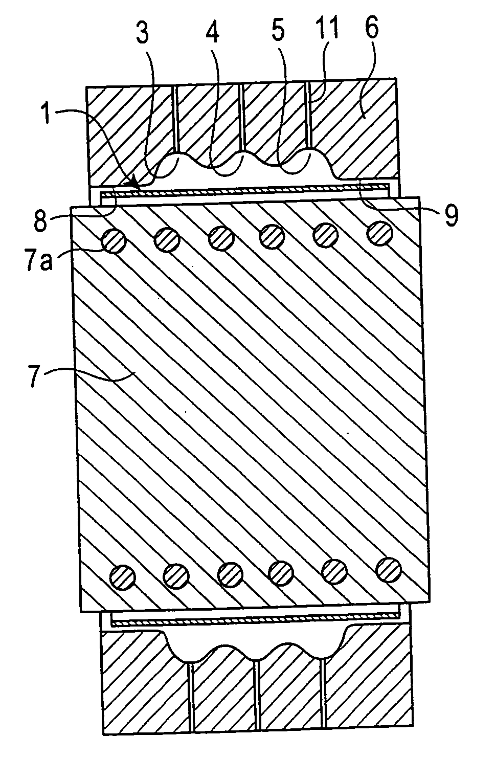
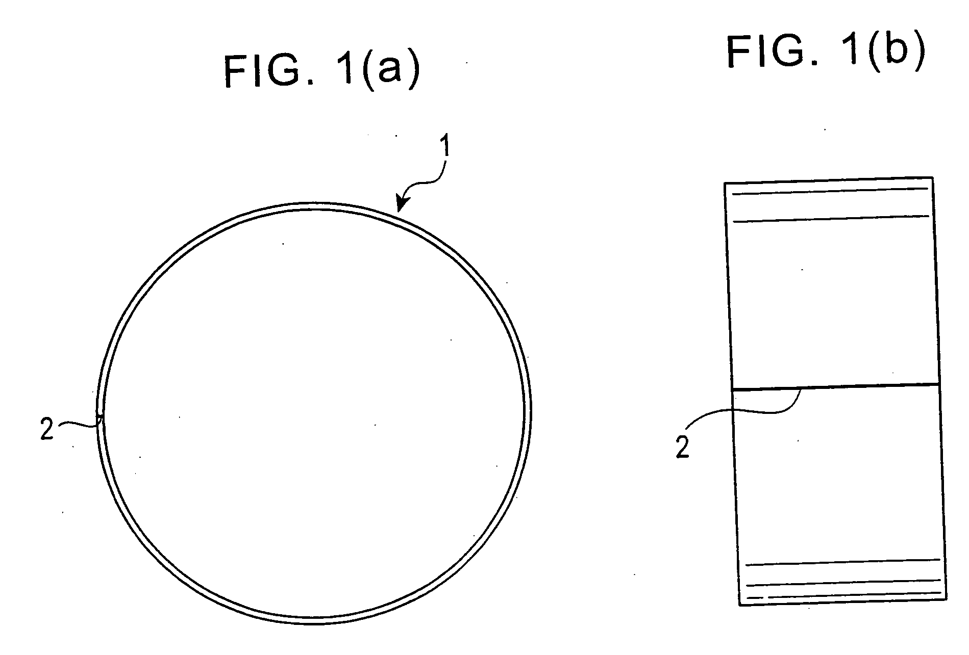
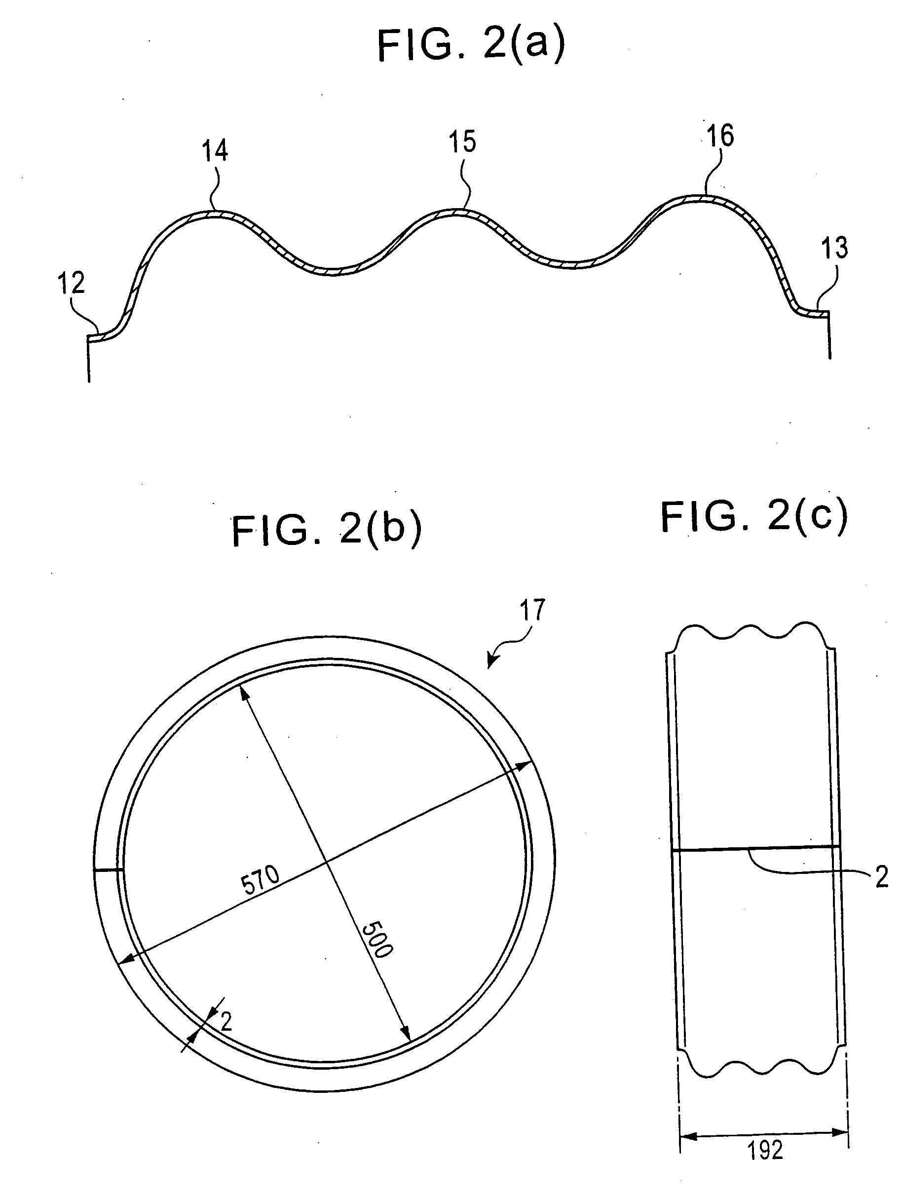
[0125] A base ring similar to that shown in FIG. 1 was molded from a plate of an aluminum alloy, and a cylindrical ring with beads was produced by molding the base ring by electromagnetic forming.

[0126] The aluminum-alloy plate as a raw material was an extruded plate (type 6061-F). The plate was formed into a cylinder by roll-bending using three rolls such that the extruding direction corresponded to the feeding direction of the roll-bending, and the ends were butt-welded (the connecting portion was parallel to the central axis direction of the ring). The cylindrical ring had a thickness of 2.2 mm, an internal diameter of 494 mm, and a width of 222 mm in the axial direction. For welding, laser welding and MIG welding were performed. The laser welding was performed under a condition with a power of 40 kW, a speed of 3 m / min, a wire A5356WY with a diameter of 1.2 mm, a feeding speed of 4 m / min, and an atmospheric gas of 100% argon supplied at 25 l / min. The MIG welding was performed u...


PUM


Abstract

A metal mold is disposed adjacent to the outer circumference of a base ring, and has a molding face in the inner circumference and a plurality of grooves for forming beads on the molding face along the circumferential direction. A coil for electromagnetic forming is disposed adjacent to the inner circumference of the base ring. When a momentary large current is applied to the coil in this arrangement, the diameter of the base ring is expanded by pressing the base ring toward the molding face of the metal mold such that the base ring is molded into a shape corresponding to the molding face by electromagnetic forming. Improvements such as a metal mold capable of degassing, a separable metal mold, roll-correcting after electromagnetic forming, application of momentary large current over several times, a metal mold with a cutting blade, use of a base ring with a large number of holes, and a metal mold with positioning means are then added. With these improvements, a highly accurate cylindrical ring with beads can be produced at low cost and with high productivity.

Description

TECHNICAL FIELD [0001] The present invention relates to methods for manufacturing cylindrical rings with beads available to, for example, reinforced rings for run-flat tires, and relates to metal molds used for the methods. BACKGROUND ART [0002] Electromagnetic forming is a method in which a momentary large current is applied to a coil to generate a strong magnetic field such that an object (conductor) disposed in the magnetic field is molded by an interaction between an eddy current generated at the object and the magnetic field. The electromagnetic forming is a known technique disclosed in, for example, Japanese Unexamined Patent Application Publication Nos. 6-312226, 9-166111, 58-4601, and the like. The momentary large current is a current with a value of, for example, 10 kA or more. [0003] Japanese Unexamined Patent Application Publication No. 6-312226 discloses an application of this electromagnetic forming to processing of a cylindrical member (hollow workpiece). According to ...

Claims


Application Information

Patent Timeline
IPC IPC(8): B21D26/02B60C17/04B21D26/14B21D39/08B21D53/16B21D53/30B60C17/06
CPCB21D26/14Y10T29/49803B21D53/16
Inventor IMAMURA, YOSHIHAYAEGUCHI, NORITAKASAKURAI, TAKEOTANIMOTO, HIROSHI
Owner BRIDTONE 50
Why Eureka
Try Eureka