In-process vision detection of flaws and FOD by back field illumination

a back field illumination and in-process technology, applied in the direction of investigating composite materials, controlling lamination, transportation and packaging, etc., can solve the problems of foreign objects and debris (fod), such as resin balls and fuzz balls, that can accumulate foreign objects and debris during the placement of composite strips on the underlying composite structure, and achieve the effect of simplifying the composite structure inspection process and minimizing the time involved

Inactive Publication Date: 2006-05-25
THE BOEING CO
View PDF79 Cites 34 Cited by
  • Summary
  • Abstract
  • Description
  • Claims
  • Application Information

AI Technical Summary

Benefits of technology

[0011] The embodiments of the present invention provide several advantages. One such advantage is the provision of a composite structure in-process fabrication inspection technique that allows for the simultaneous detection of flaws and FOD for a single field of inspection.
[0012] Another advantage provided by an embodiment of the present invention, is the provision of a composite structure in-process fabrication inspection technique that allows for the simultaneous detection of flaws and FOD using a single illumination level.
[0013] Furthermore, the present invention simplifies the composite structure inspection process and minimizes the time involved therein.

Problems solved by technology

Unfortunately, defects can occur during the placement of the composite strips onto the underlying composite structure.
Such defects can include tow gaps, overlaps, dropped tows, puckers, and twists.
Additionally, foreign objects and debris (FOD), such as resin balls and fuzz balls, can accumulate on a surface of the composite structure.
In the meantime, the fabrication process has been disadvantageously slowed by the manual inspection process and machine downtime associated therewith.
The flaws in the composite structure are detectable within the bright field, but are indistinguishable in the dark field.
The use of dual illumination levels complicates the inspection process by causing a single field to be viewed twice, which is time consuming.

Method used


Image

  • In-process vision detection of flaws and FOD by back field illumination
  • In-process vision detection of flaws and FOD by back field illumination
  • In-process vision detection of flaws and FOD by back field illumination

Examples


Embodiment Construction

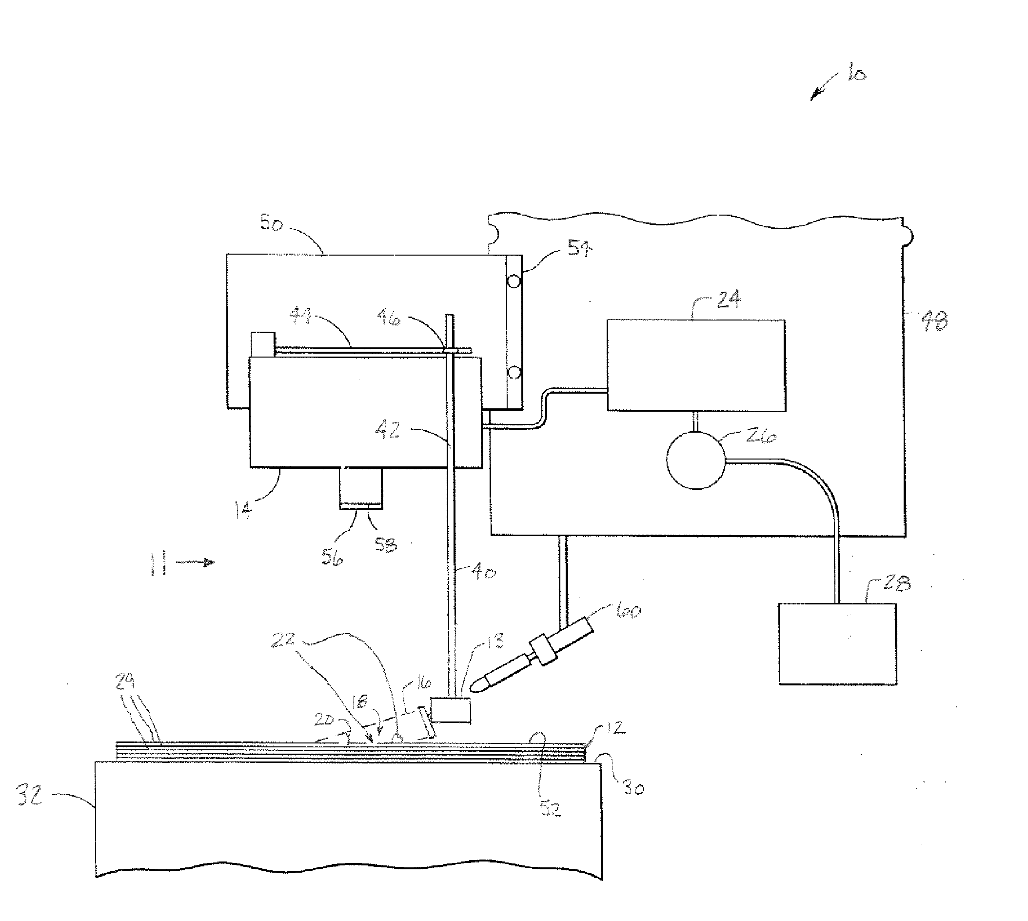
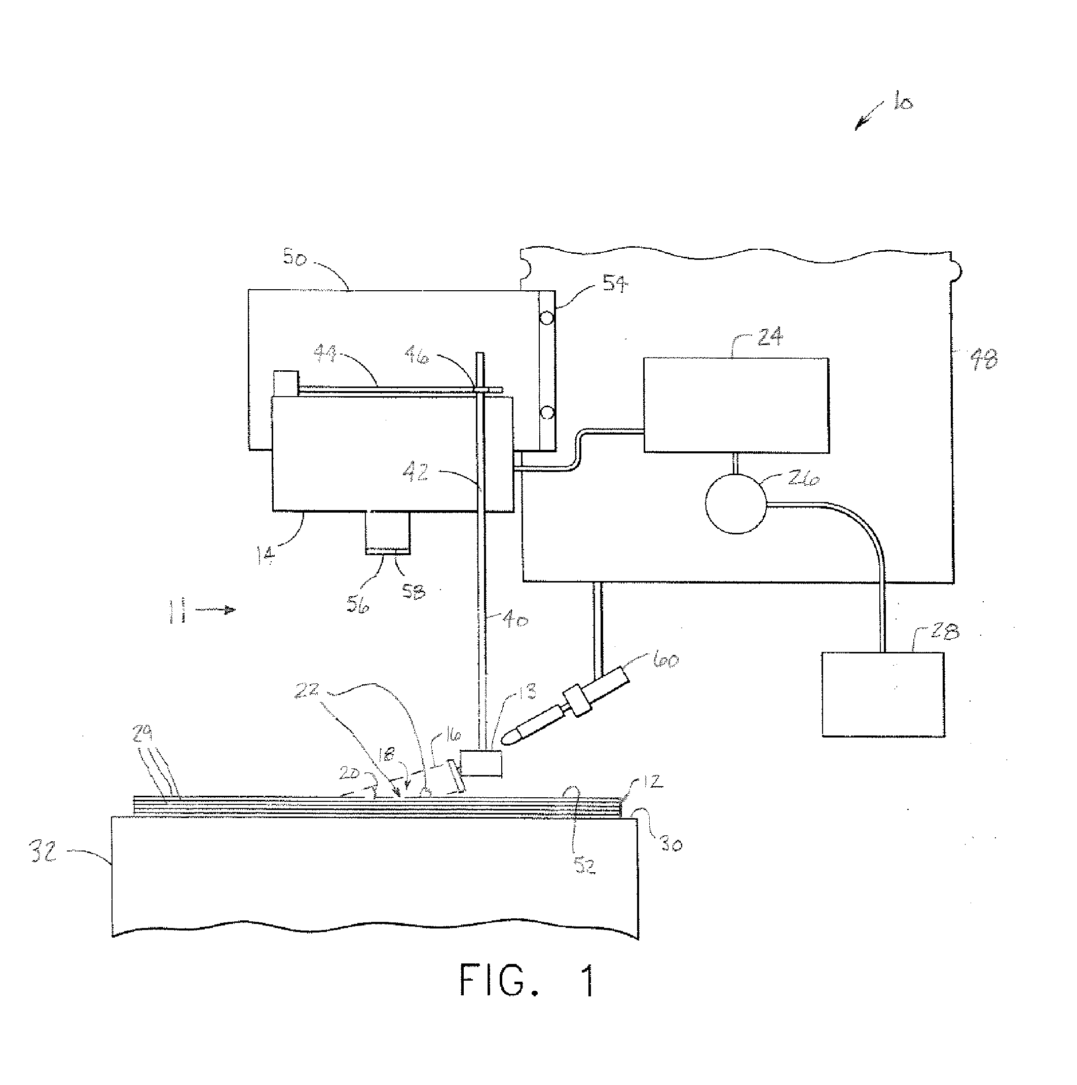
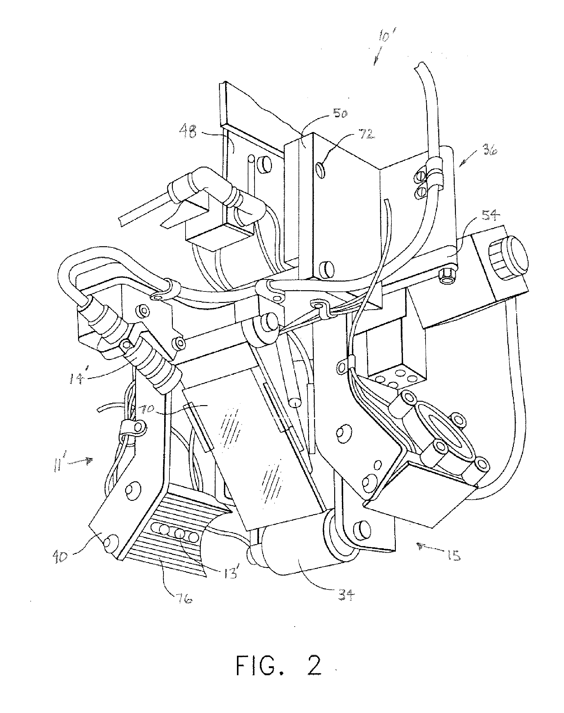
[0024] In each of the following Figures, the same reference numerals are used to refer to the same components. While the present invention is described with respect to systems and methods of detecting flaws and foreign object debris (FOD) during the fabrication of a composite structure, the present invention may be adapted for various applications and systems, such as fabrication of structures and components, production line applications, or other applications and systems known in the art. The present invention may be applied to both the fabrication of aeronautical and non-aeronautical systems and components.

[0025] In the following description, various operating parameters and components are described for one constructed embodiment. These specific parameters and components are included as examples and are not meant to be limiting.

[0026] Also, in the following description the term “foreign object debris (FOD)” refers to any resin ball, fuzz ball, impurity, or other foreign or undes...


PUM

PropertyMeasurementUnit
anglesaaaaaaaaaa
anglesaaaaaaaaaa
acute anglesaaaaaaaaaa

Abstract

A flaw and foreign object debris (FOD) detection system (11) for use during fabrication of a structure (12) includes an illumination device (13). The illumination device (13) is configured to be in proximity with a fabrication system (10) and illuminates a portion (18) of the structure (12). The illumination device (13) directs light rays (16) at acute angles relative to the portion (18). A detector (14) monitors the portion (18) and detects FOD in the portion (18) during fabrication of the structure (12) in response to the reflection of the light rays (16) off of the portion (18).

Description

TECHNICAL FIELD [0001] The present invention relates generally to the fabrication of composite structures. More particularly, the present invention relates to systems and methods of detecting flaws and foreign object debris (FOD) during the fabrication of a composite structure. BACKGROUND OF THE INVENTION [0002] Composite structures have been known in the art for many years. Although composite structures can be formed in many different manners, one advantageous technique for forming composite structures is a fiber placement or automated collation process. According to conventional automated collation techniques, one or more ribbons of composite material, known as composite strands or tows, are laid down on a substrate. The substrate may be a tool or mandrel, but more conventionally, is formed of one or more underlying layers of composite material that have been previously laid down and compacted. [0003] Conventional fiber placement processes in the formation of a part utilize a heat...

Claims


Application Information

Patent Timeline
Patent Type & Authority Applications(United States)
IPC IPC(8): B32B41/00B32B37/00B32B38/00
CPCB29C70/38B29C70/386G01N2021/8472
Inventor ENGELBART, ROGER W.HANNEBAUM, REEDPOLLOCK, TIM
Owner THE BOEING CO
Why Eureka
Try Eureka