Structure of electromagnetic switch for starter

a technology of electromagnetic switch and structure, which is applied in the direction of magnets, contact mechanisms, magnetic bodies, etc., can solve the problems of increased overall length of switch, and wear of insulator, so as to increase the overall length of switch and increase the thickness of insulator. , increase the effect of thickness

Inactive Publication Date: 2006-05-25
DENSO CORP
View PDF7 Cites 26 Cited by
  • Summary
  • Abstract
  • Description
  • Claims
  • Application Information

AI Technical Summary

Benefits of technology

[0023] When the plunger is returned away from the core by the activity of the spring, the tapered stopper face of the insulator is fitted on the tapered hitting face of the core, so that insulator partially overlaps the core in the radius direction of the switch, that is, the insulator partially enters the core. This structure permits the insulator to be increased in thickness without the need for increasing the overall length of the switch. The increasing of the thickness of the insulator results in an increased mechanical strength of the insulator.
[0024] The engagement of the tapered stopper face of the insulator with the tapered hitting face of the core increases the accuracy in centering the shaft, thereby ensuring the stability in assembling the switch in the starter. The engagement also minimizes the inclination or deflection of the insulator to avoid exertion of a undesirable biasing force on the insulator, thus permitting the mechanical strength of the insulator to be selected to be minimum. This allows the insulator to be made of an inexpensive material.

Problems solved by technology

The above switch has the moving contact installed to be rotatable relative to the insulator and, thus, encounters the drawback in that relative rotation between the moving contact and the insulator due to mechanical vibrations of the switch will result in wear of the insulator, thus requiring the need for increasing the size of the insulator enough to compensate for such wear, which leads to an increased overall length of the switch.
This requires increasing the thickness of the insulator, thus resulting in an increased overall length of the switch.

Method used


Image

  • Structure of electromagnetic switch for starter
  • Structure of electromagnetic switch for starter
  • Structure of electromagnetic switch for starter

Examples


first embodiment

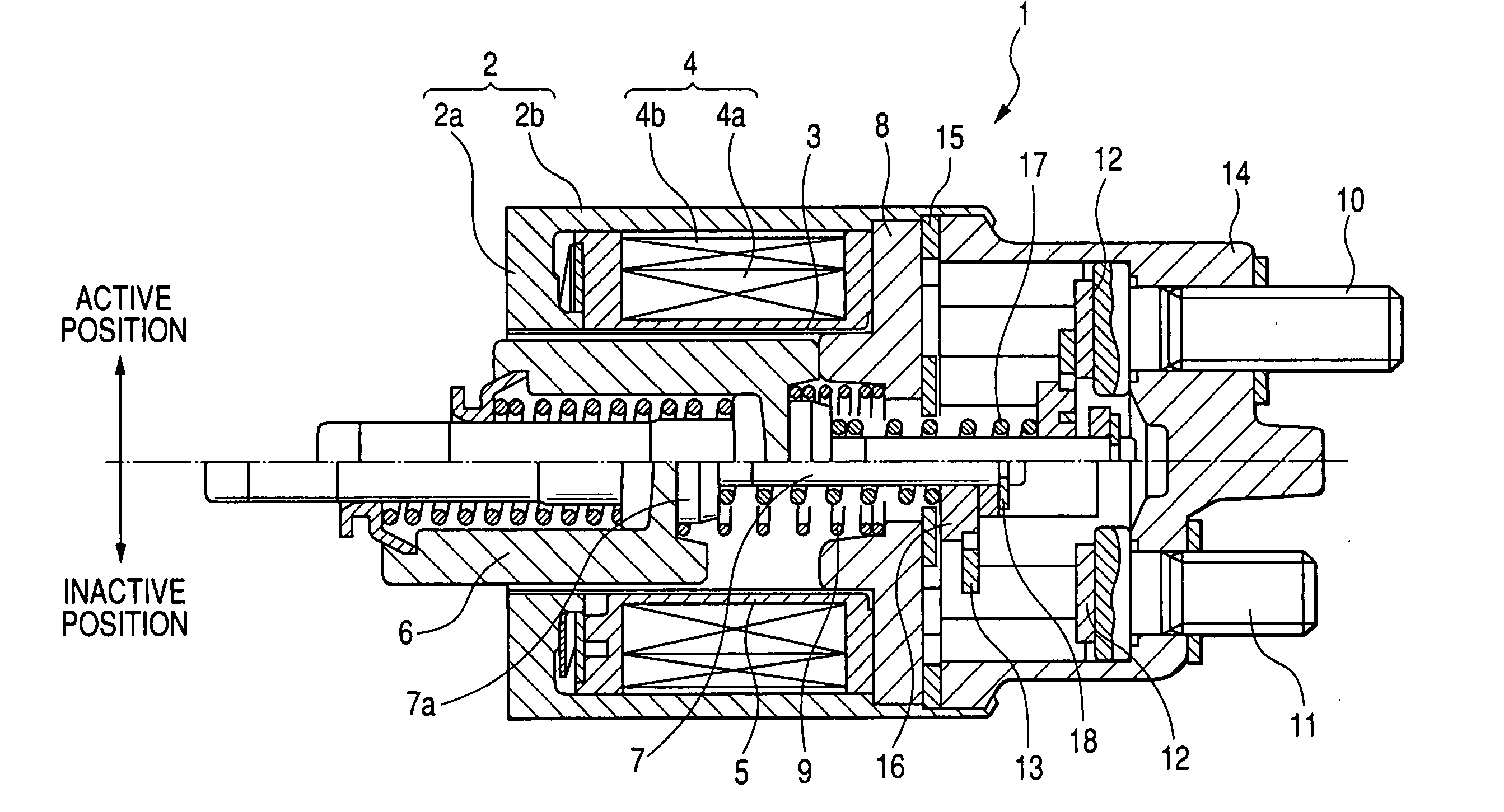
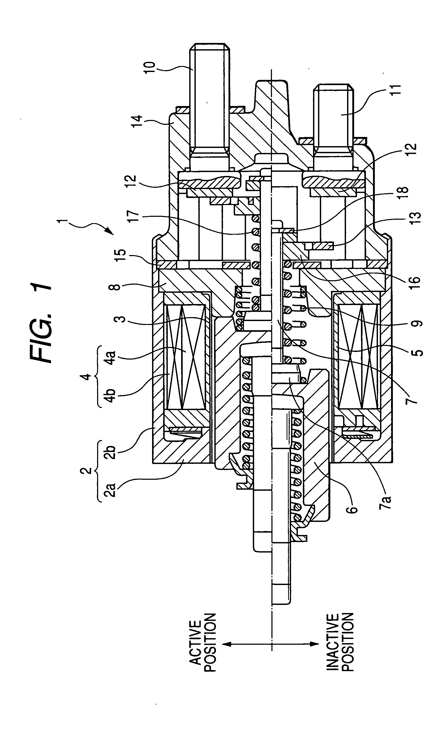
[0066] Referring now to the drawings, wherein like reference numbers refer to like parts in several views, particularly to FIG. 1, there is provided an electromagnetic switch 1 according to the invention which is used in actuating a starter for automotive engines, for example.

[0067] The electromagnetic switch 1 includes a cup-shaped yoke 2, an exciting coil 4, a plunger 6, a plunger shaft 7, and a motor contact assembly (will be described later in detail). The exciting coil 4 is wound round a bobbin 3 and disposed inside the yoke 2. The plunger 6 is disposed inside the bobbin 3 through a sleeve 5. The plunger shaft 7 is fixed to the plunger 6. The motor contact assembly works to open or close a motor circuit (i.e., a motor driver) of a starter.

[0068] The yoke 2 is made up of a bottom wall 2a and a cylindrical peripheral wall 2b. The bottom wall 2a has a circular center opening formed therein. The peripheral wall 2b extends from the circumference of the bottom wall 2a to cover the e...

second embodiment

[0082] The electromagnetic switch 1 will be described below.

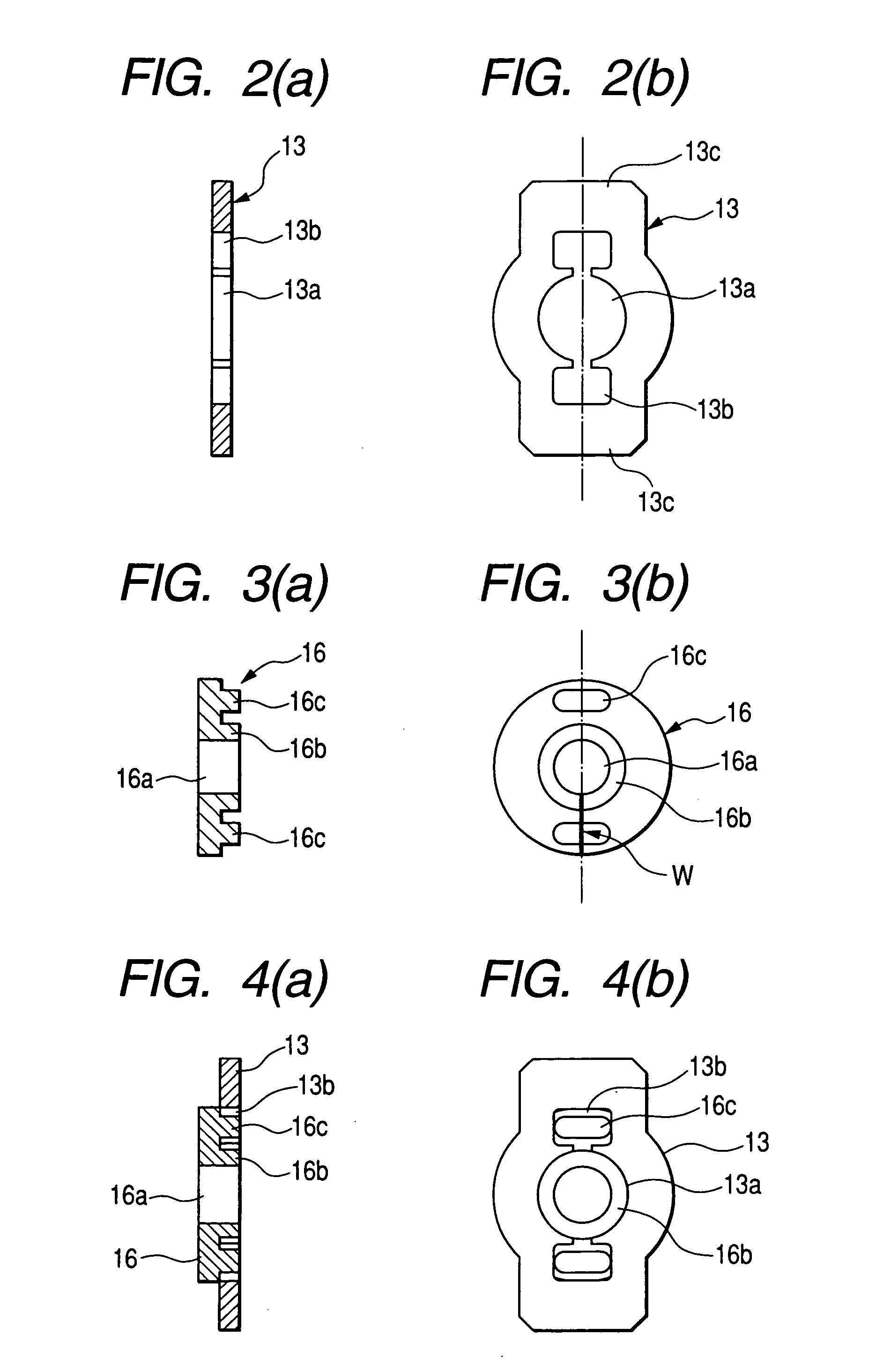
[0083] The insulator 16, as used in this embodiment, is made of a resin mold. The moving contact 13 is, like the first embodiment, held by the inner periphery of the contact cover 14 from rotating and allowed to move in the axial direction of the plunger shaft 7, so that the moving contact 13 always hits at the same areas (i.e., the contact areas 13c in FIG. 2(b)) on the fixed contacts 12.

[0084] When the moving contact 13 is moved by the magnetic attraction acting on the plunger 6 and hits the fixed contacts 12, it will cause a physical impact to act on the insulator 16 through the moving contact 13. Since the moving contact 13 always hits at the same areas on the fixed contacts 12 and is held from rotating relative to the insulator 16, a maximum impact load is always exerted on the same potion of the insulator 16. Specifically, when the moving contact 13 hits the fixed contacts 12, the insulator 16 undergoes the impact l...

fourth embodiment

[0102] The electromagnetic switch 1 will be described below.

[0103] The electromagnetic switch 1 is so designed that the clearance C1 between the plunger 6 and the sleeve 5 and the clearance C2 between the outer periphery of the insulator 16 and the inner wall of the recess of the stationary core 8 meet a relation of C12. This prevents the insulator 16 from riding on the end face 8b of the stationary core 8 when the plunger 6 is shifted or inclined in the radius direction within the sleeve 5, thus ensuring the stability in returning the plunger 6 away from the stationary core 8.


PUM


Abstract

An electromagnetic switch for use in actuating a starter for automotive vehicles is provided. The switch includes fixed contacts, a moving contact, and a plunger shaft. The moving contact is joined to a plunger shaft through an insulator. The plunger shaft is to be moved magnetically to bring the moving contact into abutment with the fixed contact to establish electric communication between the fixed contact. The switch also includes a rotation holder working to hold the moving contact and the insulator from rotating relative to each other. Use of the rotation holder results in a decrease in wear of the insulator. This eliminates the need for the insulator to have an additional thickness which would be worn down, thus permitting the insulator to be reduced in thickness to shorten the overall length of the switch.

Description

CROSS REFERENCE TO RELATED DOCUMENT [0001] The present application claims the benefits of Japanese Patent Application Nos. 2004324189, 2004-324212, 2004-364584, and 2064-366398 filed on Nov. 8, 2004, Nov. 8, 2004, Dec. 16, 2004, and Dec. 17, 2004, respectively, disclosures of which are totally incorporated herein by reference. BACKGROUND OF THE INVENTION [0002] 1 Technical Field of the Invention [0003] The present invention relates generally to an electromagnetic switch for use in opening or closing contacts of a motor driver for automotive engine starters. [0004] 2 Background Art [0005] There are known electromagnetic switches for use in a motor driver for engine starters. For instance, Japanese Patent First Publication No. 3-969 discloses an electromagnetic switch which includes a pair of fixed contacts to be joined to a motor driver and a moving contact retained on an end of a plunger shaft through an insulator. The moving contact is brought by the plunger shaft into abutment wit...

Claims


Application Information

Patent Timeline
Patent Type & Authority Applications(United States)
IPC IPC(8): H01H67/02
CPCH01H1/20H01H51/065
Inventor HIRABAYASHI, TAKASHIKURASAWA, TADAHIROUSAMI, SHINJI
Owner DENSO CORP
Why Eureka
Try Eureka