Camera lens

a technology for camera lenses and lens barrels, applied in the field of camera lenses, can solve the problems of increasing material costs, increasing the cost of assembling and mounting the lens elements into the barrel affecting the quality so as to reduce the volume of the camera lens, eliminate the effect of spherical aberration and easy mass production

Inactive Publication Date: 2006-05-25
HON HAI PRECISION IND CO LTD
View PDF6 Cites 5 Cited by
  • Summary
  • Abstract
  • Description
  • Claims
  • Application Information

AI Technical Summary

Benefits of technology

[0009] The camera lens comprises a single aspheric lens having a phase grating. Because the camera lens does not comprise any spherical lens, spherical aberrations can be eliminated, and the volume of the camera lens can be reduced. In addition, the camera lens does not need a conventional barrel, and can instead be directly mounted in a portable electronic device such as a digital camera. Further, because the camera lens is made by plastic injection molding, it can be readily mass manufactured. Therefore, the cost of the camera lens can be reduced while providing high quality.
[0010] As a further improvement of the present invention, a film coating is plated on surfaces of the spherical lenses for improving the image quality and for protecting the camera lens from physical damage.

Problems solved by technology

Camera lenses having a large number of lens elements tend to be large, heavy, and expensive to manufacture.
The large number of lens elements increases material costs, and increases the cost of assembling and mounting the lens elements into the barrel of a camera lens.
Aspheric glass lens elements may be produced through glass molding methods, but the cost of this kind of method is higher compared to methods of manufacturing aspheric plastic lens elements.
In addition, aspheric glass lens elements generally have poor resistance to strong impact, and are easily damaged.
Furthermore, glass lens elements are heavier than plastic lens elements, and militate against the trend toward lightweight digital cameras.
However, the overall weight of the lens is unduly great.
In addition, the lens elements are easily damaged if they are subjected to shock, such as when a digital camera is dropped to the ground.
Furthermore, the spherical lens elements are apt to produce spherical aberration, thereby diminishing the image quality.
However, the impact resistance of the lens is still rather weak, and the lens may be easily damaged if the corresponding digital camera is dropped to the ground.

Method used


Image

  • Camera lens
  • Camera lens

Examples


Embodiment Construction

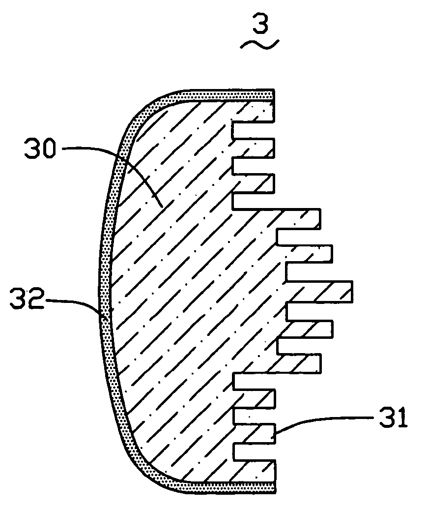
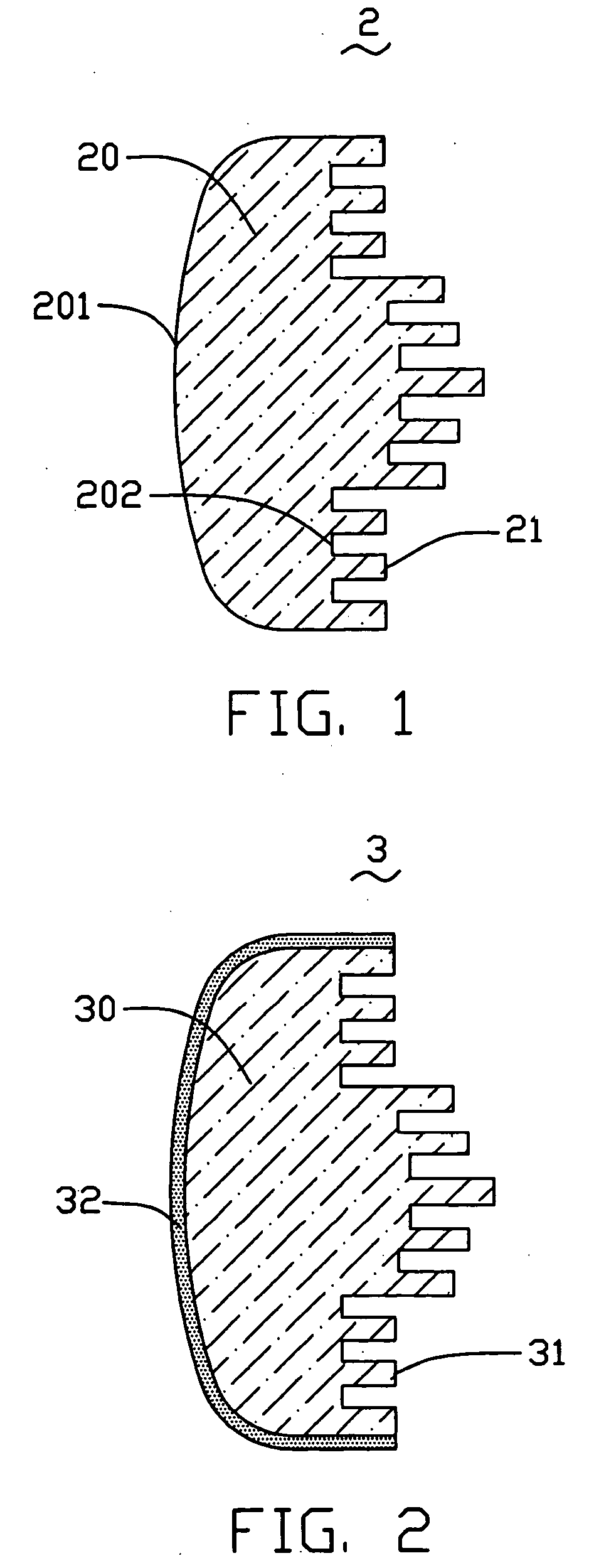
[0014] Referring to FIG. 1, a camera lens 2 of a first preferred embodiment includes an aspheric lens 20 and at least one phase grating 21. The aspheric lens 20 is made of plastic material such as PMMA (polymethyl methacrylate) or PC (polycarbonate), and includes a first optical surface 201 and a second optical surface 202. At least one of the first optical surface 201 and the second optical surface 202 is an aspheric surface. The phase grating 21 is a binary phase grating formed at one of the first optical surface 201 and the second optical surface 202 of the aspheric lens 20. Preferably, the phase grating 21 is formed at the second optical surface 202.

[0015] The method of manufacturing the camera lens 2 includes the following steps: firstly, designing the shape and the structure of the aspheric lens 20 and the phase grating 21; secondly, designing a mold (not shown) according to the shape and the structure of the aspheric lens 20 and the phase grating 21; and finally, injecting a...


PUM


Abstract

A camera lens (2, 3) for a portable electronic device includes an aspheric lens (20, 30) and at least one phase grating (21, 31). The aspheric lens includes a first optical surface (201) and a second optical surface (202). At least one of the two optical surfaces is an aspheric surface and at least one phase grating is formed with the aspheric lens in a whole. The phase grating is formed at one of the first optical surface and the second optical surface of the aspheric lens. The camera lens comprises a single aspheric lens having a phase grating. Because the camera lens does not comprise any spherical lens, spherical aberrations can be eliminated, and the volume of the camera lens can be reduced.

Description

FIELD OF THE INVENTION [0001] The present invention generally relates to camera lenses for portable electronic devices such as digital cameras, and more particularly to a camera lens that has a lens element with an aspheric surface. GENERAL BACKGROUND [0002] Digital cameras utilizing high-resolution electronic imaging sensors typically require high resolution optical components including lenses. These camera lenses should be very compact, so that they can be incorporated into other electronic devices such as palm-sized computers, cellular telephones, and the like. [0003] A lens for a digital camera generally has several individual lens elements. The lens elements are typically spherical, and usually create spherical aberration. Chromatic aberration, coma, distortion, and field curvature are also common optical aberrations that occur in the imaging process of a typical lens. A large number of lens elements are generally required in order to balance the inherent optical aberrations. C...

Claims


Application Information

Patent Timeline
Patent Type & Authority Applications(United States)
IPC IPC(8): G02B13/18G02B3/04G02B3/08G02B5/18
CPCG02B3/04G02B3/08G02B5/1871
Inventor CHEN, GA-LANE
Owner HON HAI PRECISION IND CO LTD
Why Eureka
Try Eureka