
Method for detecting linear image in planar picture

a linear image and planar image technology, applied in the field of linear image detection in planar pictures, can solve the problems of large amount of space debris (space garbage) of various sizes, high impact energy, and increased risk of space debris or astronauts performing a journey outside the craft, etc., to achieve short exposure time, short exposure time, and image satisfactorily

Inactive Publication Date: 2006-05-25
JAPAN SCI & TECH CORP +1
View PDF1 Cites 16 Cited by
  • Summary
  • Abstract
  • Description
  • Claims
  • Application Information

AI Technical Summary

Benefits of technology

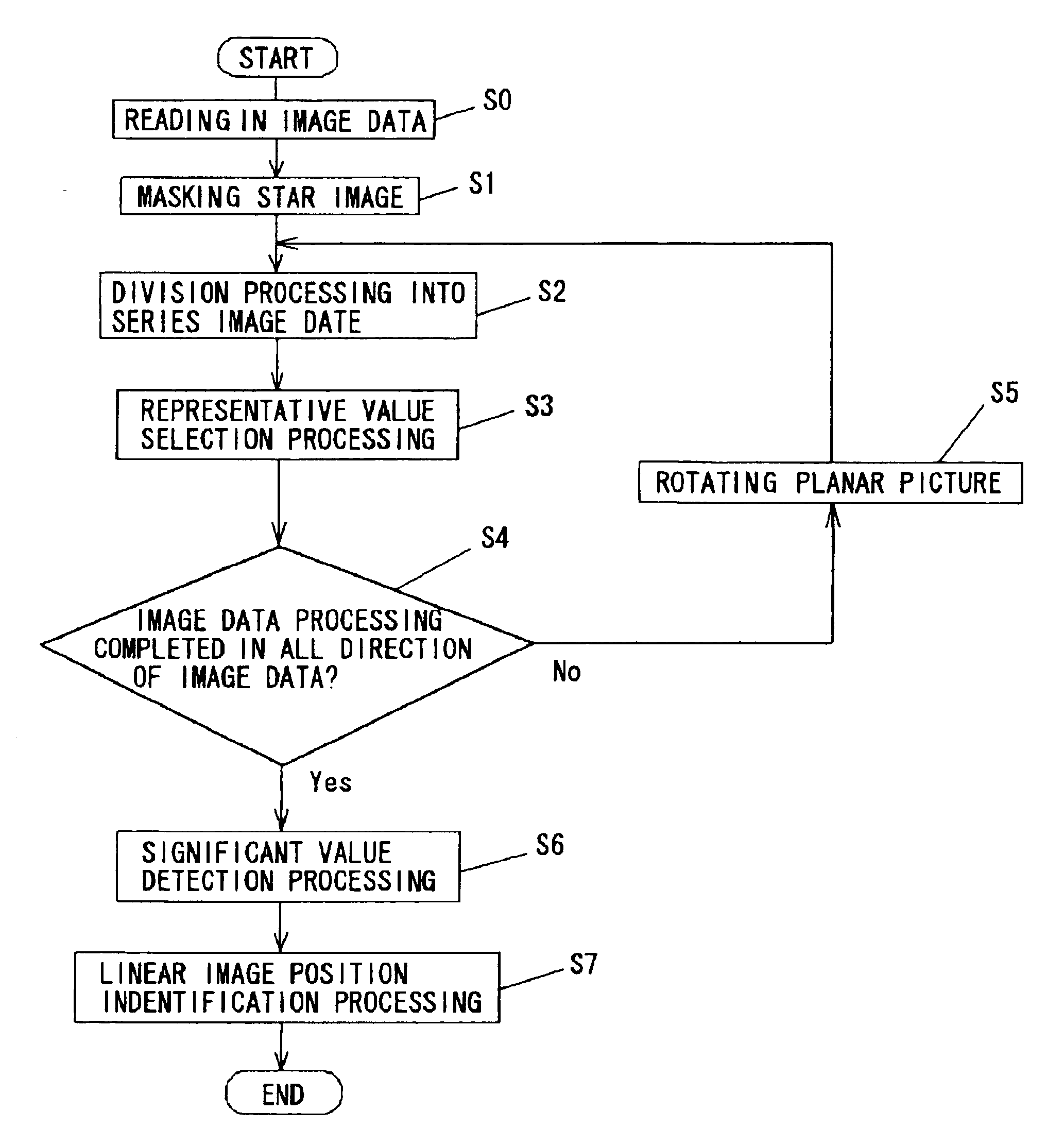
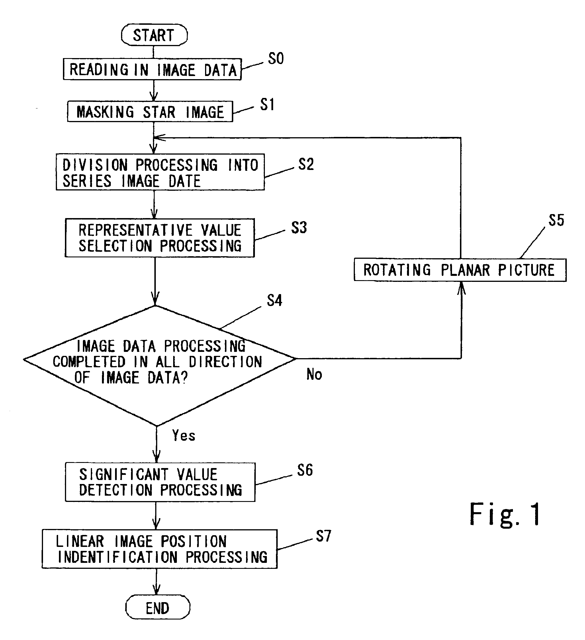
[0014] If it is supposed that, in performing image data processing in all directions of the planar picture, the columnar image data divided in a particular direction coincides with the linear image, then the image data belonging to that columnar image data will be almost entirely affected by the presence of the linear image, even if it is obscured by noise, and hence a significant value will appear as the median value, from which it will be recognisable that it coincides with a linear image. The analysis processing performed after the image data processing has been completed in all directions of the planar picture consists of: significant value detection processing for detecting whether or not the representative value of each of the columnar image data is a significant value, and linear image position identification processing for identifying the linear position of columnar image data having a representative value indicating a significant value as the position of a linear image. In the significant value detection processing, representative values indicating significant values are detected from the sets of representative values obtained by the image data processing performed in every direction of the planar picture, and in the linear image position identification processing, the linear position of columnar image data having a representative value indicating a significant value is taken as the position of a linear image in the picture. In this way, it is possible significantly to reduce the noise level and detect linear images below the original noise level of the original picture, by deriving the median value of each image series data in all direction of a planar picture captured by an imaging element.
[0017] In this method for detecting a linear image, desirably, if the planar picture contains an image region indicating an abnormal value for the value of the image data, due to an excessive light reception level, mask processing is performed for replacing the value of the image data in the image region with a median value of background noise, the image data processing being carried out on the basis of the image data after the mask processing has been performed. If there is a region on the planar picture having an abnormal value for the image data value due to an excessive light reception level, a large number of pixel data belonging to the same columnar image data indicate an abnormal value, then there is a possibility that the median value derived for that columnar image data will be affected by these abnormal values. Hence, by performing mask processing of the region, the aforementioned abnormal values can be excluded from the image data, and hence the effects thereof can be eliminated in advance.
[0022] In this method for detecting a linear image, desirably, the CCD imaging element is mounted on a camera having a wide angle and short exposure time, in cases where the flying object is a meteor. Since a meteor travels at a lower altitude that low-orbiting debris, and moreover, since it shines very brightly due to frictional heat caused by contact with the upper atmosphere, despite the fact that it is very small in size, then it can be imaged satisfactorily even using a short exposure time. Therefore, it is possible to capture images using a camera with a small aperture but a wide imaging angle covering a broad field of view.

Problems solved by technology

With the progress of space exploration in recent years, the number of rockets and artificial satellites launched has increased, and as a result, there is a large amount of space debris (space garbage) of various sizes, circling in the space surrounding the earth, including not only natural objects, such as space dust, but also artificial satellites, rockets and boosters which are no longer in use, or pieces or broken shards of same, or flakes of paint peeled off same, and the like.
This use of and activity in celestial space is carried out in a region of space traversed by large quantities of flying space debris, and as spacecraft and flying objects get larger in size and spend longer flight times in space, so the risk of these craft and objects, or astronauts performing a journey outside the craft, being struck by space debris gradually increases.
Although space debris only has a size of several millimeters, for example, and collisions with same are extremely rare, if a collision does occur, the impact energy will be very high, due to the extremely fast relative velocity on impact, and hence the craft or object may be damaged and the lives of the astronauts put in danger.
With increasing exploration and use of space in the future, it can be expected that the amount of space debris originating from artificial objects will rise further, and hence the danger of collision with this space debris will continue to increase.
In the Hough transform, it is necessary that the linear images appear clearly on the CCD picture, and therefore, it is not possible to provide satisfactory observation of space debris, which is small and dark and cannot be treated as a linear image on the picture.
When launch expenses are taken into account, installing an observation device in a artificial satellite or spacecraft involves very great cost.
Images captured of these objects generated contain noise, which make the objects hard to detect.

Method used


Image

  • Method for detecting linear image in planar picture
  • Method for detecting linear image in planar picture
  • Method for detecting linear image in planar picture

Examples


Embodiment Construction

[0033] An embodiment of the linear image detecting method according to the present invention is described with reference to the drawings.

[0034] The planar picture shown in FIG. 2 is a CCD picture of the sky (in this case, the night sky) captured by a camera provided with a CCD imaging element installed in a telescope. In this planar picture, a large number of stars can be identified, but the linear images of low-altitude debris or meteors, if such exist, are difficult to identify because they are obscured by noise. In the linear image detecting method for planar pictures according to the present invention, as illustrated by the flowchart in FIG. 1, the image data of this planar picture is read into a calculating device, such as a PC (S0), and mask processing (S1) for removing the star images from the picture data is performed. The image data processing for achieving a median value picture, described hereinafter, involves statistical processing where a relatively small number of irr...


PUM


Abstract

A method for detecting a linear image in a planar picture is provided whereby the positions of a linear image can be determined by devising suitable processing of image data, even if a linear image traced by a moving object, such as space debris, a meteor, or the like, does not appear clearly on a picture. Image data processing, consisting of division processing (S2) for dividing image data of a planar picture captured by an imaging element into a plurality of mutually parallel columnar image data and representative value selection processing (S3) for taking the median value determined for each of the columnar image data as a representative value for the corresponding columnar image data, is performed in every direction of said planar picture, whereupon analysis processing consisting of significant value detection processing (S6) for detecting whether or not said representative value of each of said columnar image data is a significant value, and linear image position identification processing (S7) for identifying the linear position of columnar image data having a representative value indicating a significant value as the position of a linear image resulting from the passage of the moving object or the like, is performed.

Description

BACKGROUND OF THE INVENTION [0001] 1. Field of the Invention [0002] The present invention relates to a method of detecting linear images in planar pictures, whereby linear images like that traced by a moving object, such as debris following an orbit, can be detected from a planar picture depicting an object, such as a night sky, or the like, captured by means of an imaging element, such as a CCD imaging element, for example. [0003] 2. Description of the Related Art [0004] With the progress of space exploration in recent years, the number of rockets and artificial satellites launched has increased, and as a result, there is a large amount of space debris (space garbage) of various sizes, circling in the space surrounding the earth, including not only natural objects, such as space dust, but also artificial satellites, rockets and boosters which are no longer in use, or pieces or broken shards of same, or flakes of paint peeled off same, and the like. [0005] In the use of celestial sp...

Claims


Application Information

Patent Timeline
Patent Type & Authority Applications(United States)
IPC IPC(8): G06K9/00G06K9/36G06T7/60B64G1/68G06T7/00G06V10/30
CPCB64G1/68G06K9/40G06K9/50G06T7/0042G06T7/73G06V10/30G06V10/421
Inventor YANAGISAWA, TOSHIFUMINAKAJIMA, ATSUSHI
Owner JAPAN SCI & TECH CORP
Learn More