
Pulling device for container inspection system

a container inspection and pulling device technology, applied in the field of inspection systems, can solve the problems of difficult control, disadvantage of conventional pulling device of the container inspection system, excessive slack of wire rope on one side, etc., and achieve the effect of reducing the area occupied by the system and reducing the investment of equipmen

Inactive Publication Date: 2006-06-01
NUCTECH CO LTD +1
View PDF9 Cites 43 Cited by
  • Summary
  • Abstract
  • Description
  • Claims
  • Application Information

AI Technical Summary

Benefits of technology

[0008] The present invention has been made to overcome one or more of the above mentioned disadvantages. Accordingly, it is an object of the present invention to provide a pulling device for container inspection system in which the winch is configured to have a single winding drum. Accordingly, the investment of equipment is reduced and the area occupied by the system is decreased. Meanwhile, the inspection system of the present invention can provide constant tensile force which is continuously adjustable so that the operation of pulling device can be performed more reliably and more safely.
[0013] With the above construction, in the pulling device for the container inspection system of the present invention, the wire rope for driving the pulling vehicle back and forth is wound around the same winding drum. The winding drum with the constant diameter makes the wire ropes at both sides are synchronically retracted and slackened. Further, with the active type tension mechanism which generates a tensile force by use of a spring, the wire ropes are constantly kept in a state under an effective tensile force. Accordingly, the phenomenon that the wire ropes are entangled due to slack of the wire ropes will not occur. Moreover, the active type tension mechanism can make up the elongation resulting from permanent deformation of the wire ropes due to usage of long term. Compared with the prior arts, the investment of equipments is reduced and the area occupied by the system is decreased in the present invention.

Problems solved by technology

However, the conventional pulling device of the container inspection system is disadvantageous in the following aspects.
With this operation mode, it is difficult to control so as to achieve constant tensile force.
Especially at the stage that the pulling vehicle is started or stopped, it may occur that a wire rope on one side is excessively slackened.
As a result, the pulling operation can not be carried out stably, thus impeding normal operation of the inspection system.

Method used


Image

  • Pulling device for container inspection system
  • Pulling device for container inspection system

Examples


Embodiment Construction

[0017] A preferred embodiment of the present invention will be described hereinafter in detail with reference to the attached drawings, wherein the like reference numerals refer to the like elements throughout the specification. The present invention may, however, be embodied in many different forms and should not be construed as being limited to the embodiment set forth herein; rather, this embodiment is provided so that the present disclosure will be thorough and complete, and will fully convey the concept of the invention to those skilled in the art.

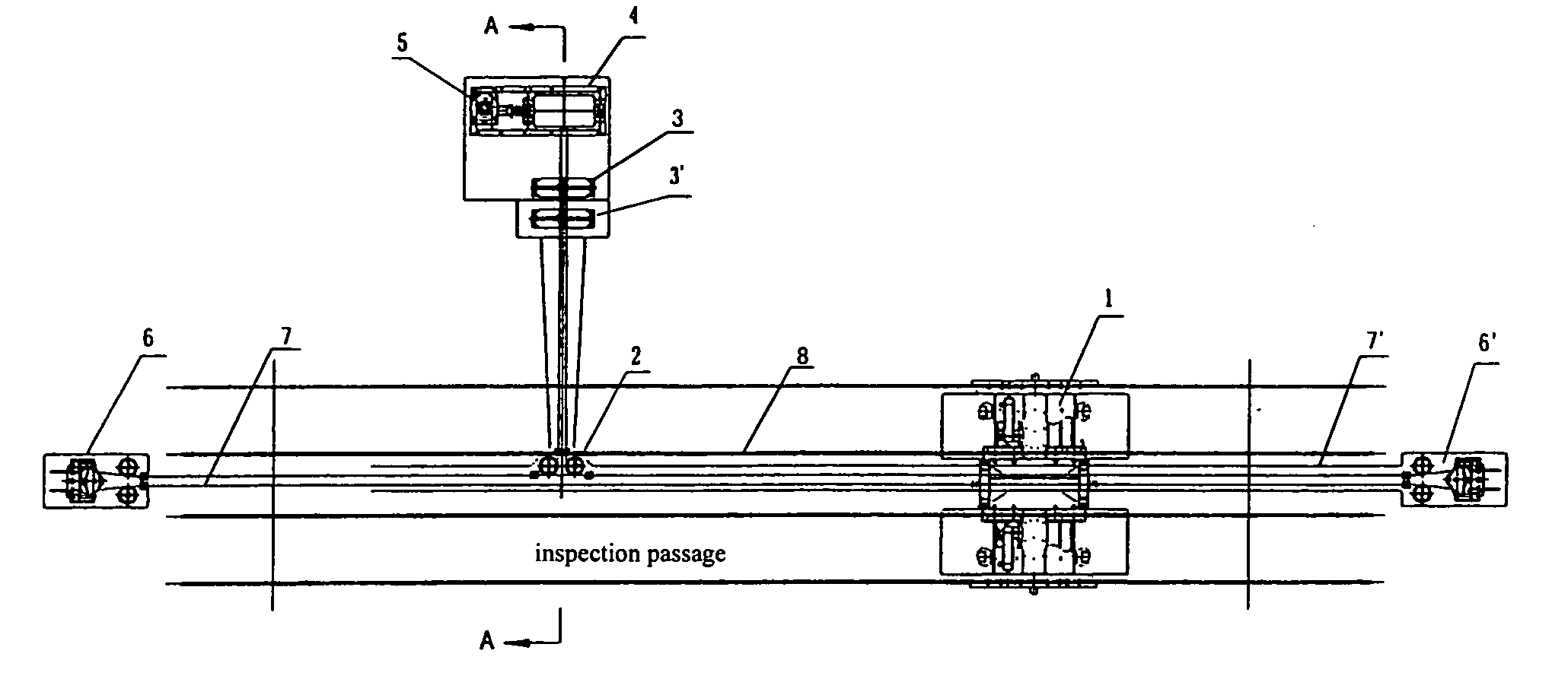
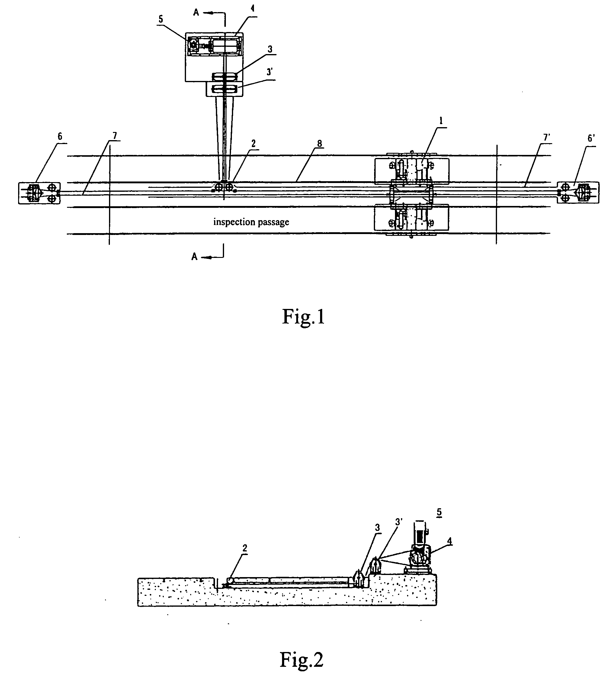
[0018] Referring to FIGS. 1 and 2, the pulling device of the container inspection system of the present invention includes a pulling vehicle, a winch 5 disposed inside an inspection passage and wire rope tension mechanisms 6,6′ disposed at front and rear ends inside the inspection passage. The wire rope tension mechanisms 6,6′ are configured to be an active tensile construction which generates tensile force by use of a spring. The pu...


PUM

PropertyMeasurementUnit
Forceaaaaaaaaaa

Abstract

The present invention discloses a pulling device for a container inspection system including a pulling vehicle (1) arranged inside an inspection passage, a winch (5) and wire tension mechanisms (6,6′). Front and rear ends of the pulling vehicle are connected to a wire rope so as to drive the pulling vehicle to move back and forth inside the inspection passage. The wire rope connected to front and rear ends of the pulling vehicle is wound around a wire tension mechanism arranged at front and rear ends of the inspection passage and is turned around by a swerving pulley (2) which is positioned at the same horizontal plane as that of the wire rope, the pulling vehicle, and the wire tension mechanisms, then the wire rope passes through the vertical pulley block, and finally it is connected to a single winding drum (4) of the winch (5) and wound around the single winding drum (4) respectively. Compared with the prior arts, the present invention is advantageous in reduction in equipment investment and decrease in area occupied by the pulling device. Further, the inspection operation can be carried out more reliably and safely.

Description

CROSS-REFERENCE TO RELATED APPLICATION [0001] This application claims the benefit of Chinese Patent Application No. 200410009891.3 filed on Nov. 26, 2004 in the State Intellectual Property Office of China, the disclosure of which is incorporated herein by reference. BACKGROUND OF THE INVENTION [0002] 1. Field of the Invention [0003] The present invention relates to an inspection system for inspecting a container by obtaining images through radiation, more particularly, to a pulling device for a container inspection system. [0004] 2. Description of the Related Art [0005] In the prior arts, the pulling type container inspection system, such as the large scale container inspection system manufactured by Haiman Corporation, Germany and British Airspace Corporation, has been developed in the early years of the nineties of 20th century. The above conventional container inspection system is devised as follows. Stationary accelerator which produces high energy x-ray as radiation source and ...

Claims


Application Information

Patent Timeline
IPC IPC(8): B65G35/00B66D1/60G01N9/24G01N33/00G01N35/04
CPCB61J3/06G01V5/0008B66D1/60G01N9/24G01N35/04G01N2033/0081G01V5/20G01N33/0081B61B9/00B66D1/30B66D1/36
Inventor HU, BINSUN, SHANGMINYANG, GUANGWU, YUCHENGYANG, ZHONGRONGJIANG, NANSHEN, WANQUANSU, JIANJUN
Owner NUCTECH CO LTD
Learn More