Organic el display

a technology of organic el and display, applied in the field of organic el (electroluminescent) display, can solve the problems of the display manufacturing process becomes more complicated, and the best, and achieves the effect of reducing mechanical stress and thermal stress, and reducing the efficiency of extracting ligh

Inactive Publication Date: 2006-06-01
SHARP KK
View PDF1 Cites 19 Cited by
  • Summary
  • Abstract
  • Description
  • Claims
  • Application Information

AI Technical Summary

Benefits of technology

[0011] In this way, in the invention, between a substrate having TFTs formed thereon and a transparent substrate that is a supporting substrate having at least color-converting layers formed thereon, an overcoat layer for gap adjustment is disposed on the transparent substrate side, and an overcoat layer for relieving stress is formed on the substrate side (i.e. the organic EL device side), this being in facing relation with no space being provided; in particular, by providing the overcoat layer for relieving stress, which has a relatively low Young's modulus, gas voids that would have an adverse effect on the display performance can be prevented from occurring at the interface with the passivation layer. That is, the overcoat layer having the lowest Young's modulus is made to be in close contact with the passivation layer within the display area, and thus fills up spaces produced by undulations caused by TFT wiring, and moreover relieves mechanical stress and thermal stress to which the organic EL display is subjected from the environment. The undulations due to the wiring on the TFT substrate are approximately 1 to 2 μm in size, and hence the thickness of the overcoat layer having the lowest Young's modulus that fills up these undulations is suitably 2 to 4 μm.

Problems solved by technology

However, with the constitution in which a fixed gap is provided using a columnar structure (support), there is a gas layer (void) having a greatly different refractive index between the organic EL layer and the color-converting filters, and hence there is much reflection of light at the interface between the gas layer and the organic EL device, and at the interface between the gas layer and the color-converting filters, and thus the efficiency of extracting light is reduced.
Moreover, with the constitution in which the gap is filled with an insulating oil or the like, this problem of reflection is alleviated, but the display manufacturing process becomes more complicated, and moreover the shock resistance, which is an intrinsic advantage of an organic EL display that is a completely solid device, is marred, and hence this constitution cannot be said to be the best.
However, with this constitution, there is a problem of damage such as peeling away of the EL device occurring through mechanical stress such as vibration or pressure or thermal stress produced, for example, through changes in the temperature of the environment in which the manufactured display is placed or during the step of bonding the organic EL device and the color-converting filters together.
However, in Japanese Patent Application Laid-open No. 11-121164, no consideration is given to adjusting the gap between the color-converting filters and the organic EL device.

Method used


Image

  • Organic el display
  • Organic el display

Examples


example

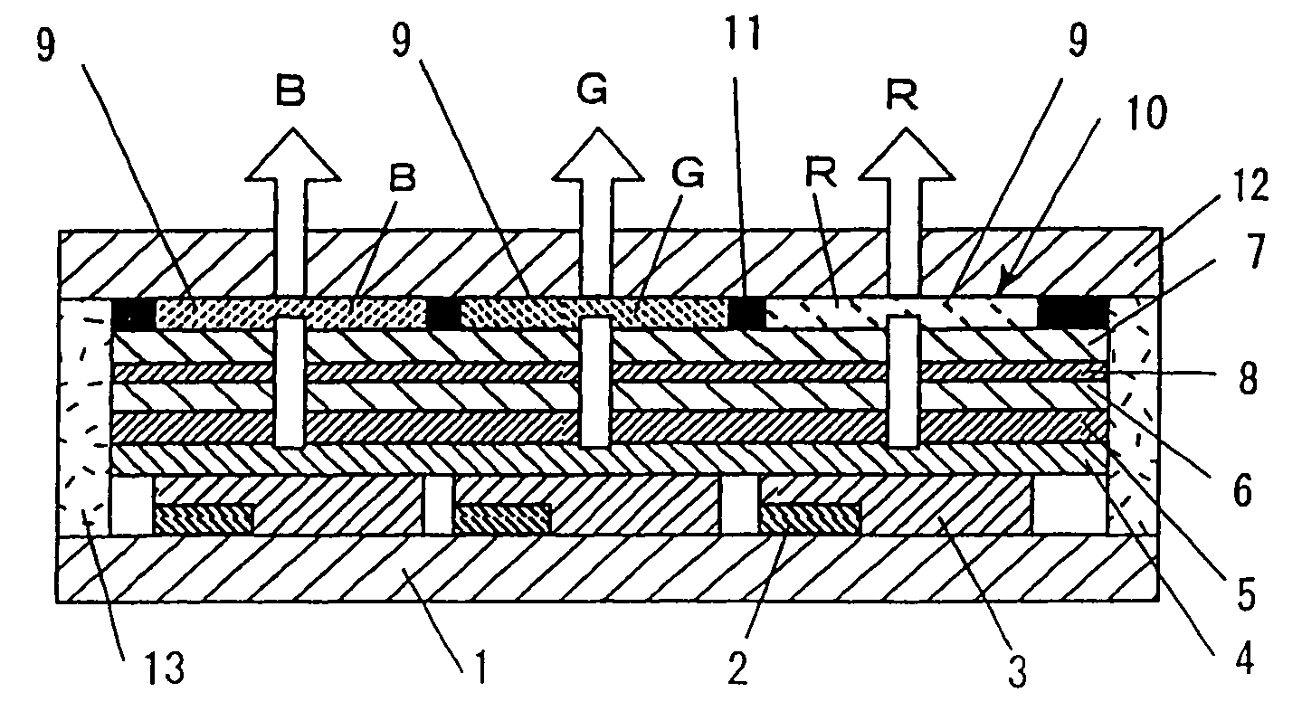
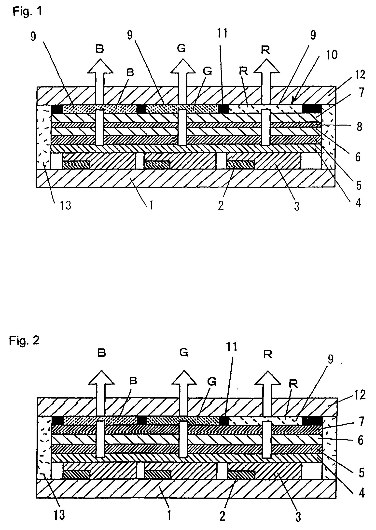
[0041] Following is a description of an example of the invention with reference to FIG. 1. FIG. 1 is a schematic sectional view of an organic EL display of the example of the invention. FIG. 2 is a comparative example in the invention.

TFT Substrate (1, 2, 3)

[0042] As shown in FIG. 1, a constitution was adopted in which bottom gate type TFTs 2 were formed on a glass (first or base) substrate 1, and the source of each TFT was connected to an anode 3.

[0043] For each of the anodes 3, aluminum, which was connected to the source of the corresponding TFT via a contact hole formed in an insulating film on the TFT, not shown, was formed as a lower part, and IZO (InZnO) was formed on the upper surface thereof.

[0044] The aluminum is provided to reflect light emitted from the light-emitting layer so that light is discharged efficiently from the top, and to reduce the electrical resistance. The thickness of the aluminum film was made to be 300 nm. The upper part IZO has a high work function...


PUM


Abstract

A top emission structure color organic EL (electroluminescent) display in which there are bonded together a substrate, having thin film transistors formed thereon, and a transparent substrate, having color-converting filters formed thereon, with an overcoat layer for adjusting the gap between the two substrates and also for relieving stress formed between the substrates without providing a space between the overcoat layers and an electroluminescent device, whereby the organic electroluminescent display has high reliability, without voids that would have an adverse effect on the display performance, and the occurrence of thermal and mechanical stress being suppressed.

Description

CROSS REFERENCE TO RELATED APPLICATION [0001] The present application incorporates herein by reference the entire disclosure and contents of the corresponding PCT application PCT / JP2003 / 007566, filed on Jun. 13, 2003. Also incorporated by reference are the entire disclosure and contents of the earlier corresponding Japanese application JP PA 2002-085485.TECHNICAL FIELD [0002] The invention relates to an organic EL (electroluminescent) display with high definition and excellent reliability, that can be used in a wide range of applications such as a display in mobile terminal equipment or industrial measuring equipment. BACKGROUND TECHNOLOGY [0003] In recent years, color organic EL displays with a driving method using thin film transistors (TFTs) have been developed. With a method in which the light is extracted from the side of the substrate on which the TFTs are formed, due to the effect of wiring parts blocking the light, the aperture ratio cannot be raised; recently, a so-called t...

Claims


Application Information

Patent Timeline
Patent Type & Authority Applications(United States)
IPC IPC(8): H01L29/82H01L27/32H01L51/52H05B33/12H05B33/14
CPCH01L27/322H01L27/3244H01L51/5237H01L51/5284H01L2251/5315H10K59/38H10K59/12H10K50/841H10K50/865H10K2102/3026G09G3/3208H05B33/12H05B33/14
Inventor KAWAMURA, YUKINORISAKURAI, KENYA
Owner SHARP KK
Why Eureka
Try Eureka