Liquid discharge head and method of manufacturing the same

Inactive Publication Date: 2006-06-01
KOHLER CO +1
View PDF36 Cites 21 Cited by
  • Summary
  • Abstract
  • Description
  • Claims
  • Application Information

AI Technical Summary

Benefits of technology

[0014] As described above, according to the liquid discharge head of the present invention, since the average sectional area of the second bubbling chamber is set to be larger than that of the first bubbling chamber, the liquid is inhibited from being evaporated on the surface of the discharge port, and discharge impossibility due to thickening of the liquid can be avoided to

Problems solved by technology

Therefore, the conventional liquid discharge head has a disadvantage that a discharge amount of ink droplets decreases with a decrease of a volume of the ink in the bubbling chamber.
Moreover, in the conventional liquid discharge head, in a case where a part of the ink with which the bubbling chamber is filled is pushed back into the supply path, a part of a pressure of the growing bubbles opposed to the side of the supply path escapes toward the supply path, or a pressure loss is generated by friction between an inner wall of the bubb

Method used


Image

  • Liquid discharge head and method of manufacturing the same
  • Liquid discharge head and method of manufacturing the same
  • Liquid discharge head and method of manufacturing the same

Examples


example 1

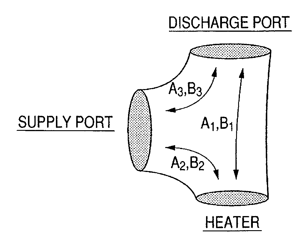
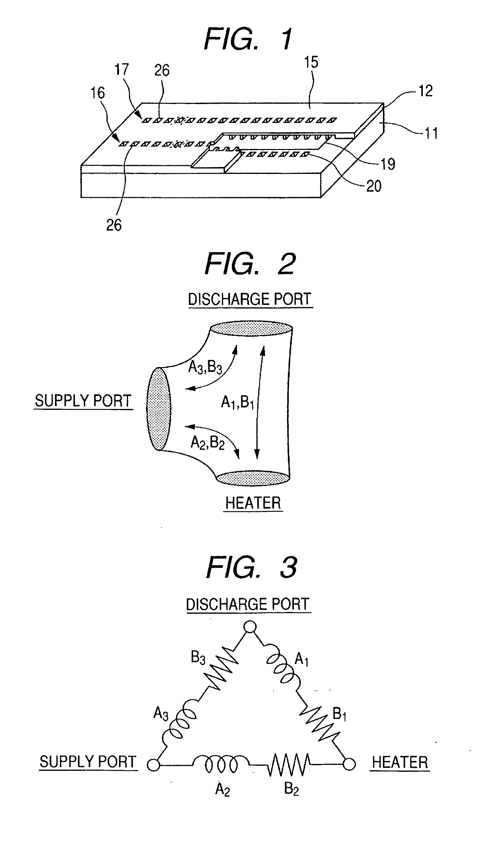
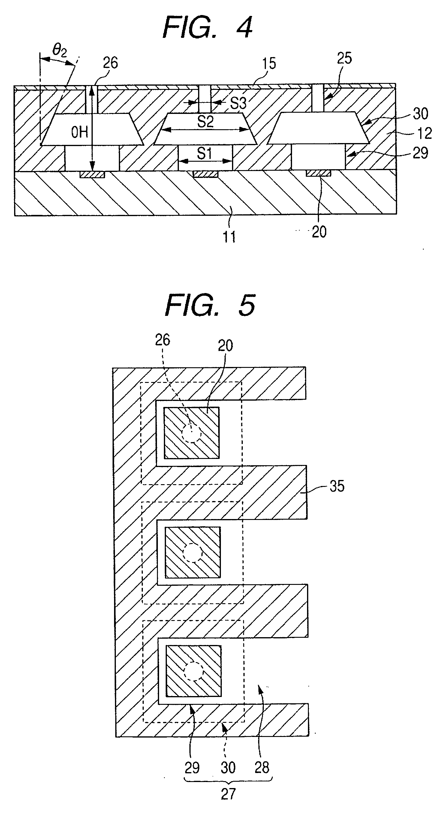
[0089] The above-described liquid discharge head has a structure in which the bubbles generated by heating the heaters 20 communicate with the outside air through the discharge ports 26 as representatively shown in FIGS. 4, 5, and 11F. Therefore, the volumes of the ink droplets discharged from the discharge ports 26 largely depend on a total volume of the ink with which the first bubbling chamber 29, the second bubbling chamber 30, and the discharge port portion 25 are filled. In other words, the volumes of the discharged ink droplets are substantially determined by a structure of a nozzle 27 portion of the liquid discharge head.

[0090] Therefore, according to the liquid discharge head of the present example, an image having a high quality level can be recorded without any ink unevenness. It is to be noted that in the liquid discharge head of Example 1, the shortest distance OH between the main surface of the heater 20 and the discharge port 26 is set to 30 μm or less in order to ve...

example 2

[0091] In a liquid discharge head of the present example, as shown in a structure of FIG. 12, a length of each discharge port portion 25 parallel to a thickness direction of the orifice substrate 12 is large as compared with the liquid discharge head of Example 1. That is, the shortest distance OH between the main surface of the heater 20 and the discharge port 26 is lengthened. In the present example, the shortest distance OH is set to about 30 μm to 75 μm. Accordingly, as to the volume of each discharge port portion 25, a structure is formed in which the average sectional area S1 of the first bubbling chamber 29, the average sectional area S2 of the second bubbling chamber 30, and the average sectional area S3 of the discharge port portion 25 satisfies a relation of S2>S1>S3 in the same manner as in Example 1.

[0092] In a case where the discharge port portion 25 is formed into an elongated cylindrical shape, the ink is usually easily secured by evaporation. However, according to t...

example 3

[0093] In the liquid discharge head of the present example, as shown in representative structures of FIGS. 13 and 14, a part 35a of the nozzle wall 35 is protruded and isolated between the supply path 28 and the first bubbling chamber 29. Moreover, the discharge port portion 25 and the first bubbling chamber 29 are filled with the ink supplied from the supply port 19 through the second bubbling chamber 30. Therefore, according to this liquid discharge head, a refill time after the bubbling is shortened as compared with that of the conventional liquid discharge head, and higher-speed recording is possible.


PUM


Abstract

According to the present invention, a discharge speed of liquid droplets is increased, a discharge amount of liquid droplets is stabilized, and a discharge efficiency of the liquid droplets is enhanced. A bubbling chamber has: a first bubbling chamber which is connected to a supply path while a main surface of an element substrate is a bottom surface and in which bubbles are generated in ink by a heater; and a second bubbling chamber connected to the first bubbling chamber. Moreover, a nozzle has a discharge port portion including a discharge port connected to the second bubbling chamber. Assuming that an average sectional area of the first bubbling chamber is S1, an average sectional area of the second bubbling chamber is S2, and an average sectional area of the discharge port portion is S3 in a section parallel to the main surface of the element substrate, the nozzle satisfies a relation of S2>S1>S3.

Description

BACKGROUND OF THE INVENTION [0001] 1. Field of the Invention [0002] The present invention relates to a liquid discharge head for discharging liquid droplets such as ink droplets to record an image on a recording material, and a method of manufacturing the head, more particularly to a liquid discharge head which records an image in an ink jet recording system. [0003] 2. Related Background Art [0004] An ink jet recording system is one of so-called non-impact recording systems. In this ink jet recording system, noises generated during the recording are so small that they can be ignored, and high-speed recording is possible. In the ink jet recording system, the recording is possible with respect to various recording materials, ink is fixed to even so-called plain paper without requiring any special treatment, and a high-definition image can be obtained inexpensively. From such advantage, in recent years, the ink jet recording system has rapidly spread as not only a printer which is a pe...

Claims


Application Information

Patent Timeline
IPC IPC(8): B41J2/05B41J2/04
CPCB41J2/1404B41J2002/14387
Inventor ASAI, KAZUHIROKUBOTA, MASAHIKOKANRI, RYOJI
Owner KOHLER CO
Why Eureka
Try Eureka