Eureka AIR delivers breakthrough ideas for toughest innovation challenges, trusted by R&D personnel around the world.

Discharging electrode structure generated by vacuum plasmas based on magnetic field effects

A plasma and discharge electrode technology, applied in the direction of plasma, electrical components, etc., can solve the problems of rapid decrease of axial energy and low plasma density, and achieve the effect of ensuring effective utilization

Active Publication Date: 2016-06-22
BEIJING JIAOTONG UNIV
View PDF8 Cites 15 Cited by
  • Summary
  • Abstract
  • Description
  • Claims
  • Application Information

AI Technical Summary

Problems solved by technology

[0007] The object of the present invention is to provide a vacuum plasma discharge electrode structure, which can not only solve the problem that the existing cone-plate electrode can only use the plasma density diffused along the radial direction of the electrode in the discharge process, but also solve the problem of cone-plate electrode. The problem of rapid axial energy decline due to radial diffusion of plasma during vacuum discharge of cylindrical electrodes

Method used


Image

  • Discharging electrode structure generated by vacuum plasmas based on magnetic field effects
  • Discharging electrode structure generated by vacuum plasmas based on magnetic field effects
  • Discharging electrode structure generated by vacuum plasmas based on magnetic field effects

Examples


Embodiment Construction

[0024] The present invention and the technical solutions in the embodiments of the present invention will be clearly and completely described below in conjunction with the accompanying drawings.

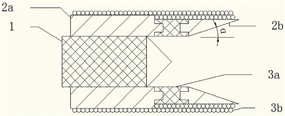
[0025] figure 1 It is a two-dimensional schematic diagram of the structure of the discharge electrode embodiment of the present invention. see figure 1 , In this embodiment, the discharge electrode includes a cathode 1 with a conical end, a ring-shaped anode 3a, a solenoid-shaped anode 3b, a cylindrical insulating member 2a, and a horn-shaped insulating member 2b.

[0026] Wherein, the cathode 1 is a structure with a conical cone at one end, and the cone is used as the discharge end of the cathode 1 . By setting the cone end as the discharge end, the discharge effect can be enhanced, and the plasma can appear in the center of the electrode, which is convenient for magnetic field confinement control, but the tip of the cone should not be too sharp, otherwise it will cause the discha...


PUM


Abstract

The invention discloses a discharging electrode structure generated by vacuum plasmas based on magnetic field effects, which is placed in a vacuum environment and comprises a cathode, an anode and an insulated part, wherein the cathode comprises a metal cylinder, one end of the metal cylinder is provided with a circular cone, and the cone end of the circular cone serves as a discharging end of the cathode; the insulated part comprises a tubular insulated part sleeving and coating the cathode, and one end of the tubular insulated part is provided with a horn-shaped radial insulated part; the anode comprises a ring anode and a spiral tube-shaped anode; one end of the tubular insulated part is connected with the horn-shaped radial insulated part via the ring anode; a single layer or multiple layers of metal wires with insulation is or are spirally wound on the insulated part to form the spiral tube-shaped anode; axes of the ring anode and the spiral tube-shaped anode and the cone end center line of the cathode circular cone are kept to be coincident; and the cathode is connected with a negative high-voltage terminal of an external circuit via a wiring column, one end of the spiral tube-shaped anode is directly connected with the ring anode, and the other end of the spiral tube-shaped anode is grounded via a wire.

Description

technical field [0001] The invention belongs to the technical field of electric propulsion applied to micro-satellites, and relates to a plasma-generated discharge electrode structure, in particular to a discharge electrode for generating high-density, high-energy, and directional jet plasma. Background technique [0002] The discharge in the vacuum environment produces metal plasma, which has high energy, and its characteristics are closely related to the electrode structure. When the arc current is small, the form of the vacuum arc is in a diffuse state, generating plasma with a certain kinetic energy. Metal plasma can be applied to ion beam surface analysis technology and ion implantation technology; for the vacuum environment of space, the electrode can be used to provide metal plasma to generate thrust without carrying additional propellants, and the discharge current can be used to flow through the anode screw. The magnetic field generated by the wire tube does not re...

Claims


Application Information

Patent Timeline
IPC IPC(8): H05H1/34H05H1/04
CPCH05H1/04H05H1/34
Inventor 刘文正窦志军陈修阳崔伟胜
Owner BEIJING JIAOTONG UNIV
Why Eureka
Eureka Blog
Learn More