Manufacturing method of ink jet recording head and ink jet recording head manufactured by manufacturing method

a manufacturing method and ink jet technology, applied in the field of manufacturing methods of ink jet recording heads, can solve the problems of unstable discharge direction of ink at the discharge port, and achieve the effect of superior discharge stability of droplet ink and high yield

Inactive Publication Date: 2005-06-30
CANON KK
View PDF7 Cites 14 Cited by
  • Summary
  • Abstract
  • Description
  • Claims
  • Application Information

AI Technical Summary

Benefits of technology

[0012] According to the present invention, the following effects can be obtained by means of the above-mentioned configuration. That is to say, a plasma composed of a mixed gas of oxygen and chlorine is used for forming a discharge port in a liquid flow path constituting member by dry etching, which makes it possible to form a discharge port having no columnar dregs therein. As a result, an ink jet recording head superior in the discharge stability of droplet ink can be obtained at a high yield.

Problems solved by technology

The columnar dregs hinder the flow of ink in the flow path or make the discharge direction of the ink at the discharge port unstable at the time of discharging the ink.

Method used


Image

  • Manufacturing method of ink jet recording head and ink jet recording head manufactured by manufacturing method
  • Manufacturing method of ink jet recording head and ink jet recording head manufactured by manufacturing method
  • Manufacturing method of ink jet recording head and ink jet recording head manufactured by manufacturing method

Examples


example 1

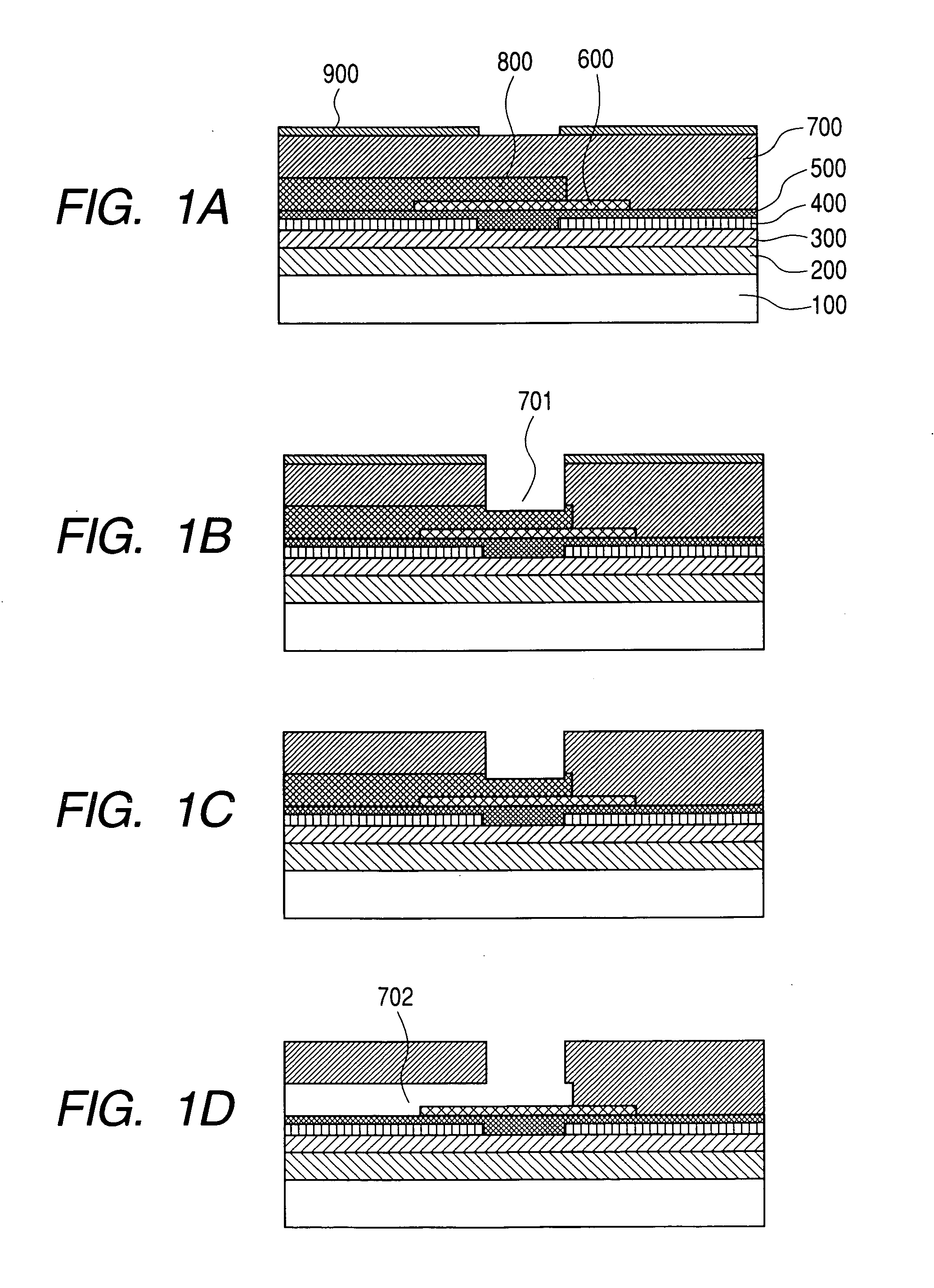
[0030]FIGS. 1A to 1D show sectional views of the processes of an embodiment of an ink jet recording head of the present invention.

[0031] Among the FIGS. 1A to 1D, FIG. 1A shows a state in which resist to be a shape member (a liquid flow path pattern) 800 is coated on a substrate 100 having a heating resistor to be patterned before a photosensitive epoxy resin to be a liquid flow path constituting member 700 is coated to be cured, and then a Si including resist 900 is patterned on the epoxy resin.

[0032]FIG. 1B shows a state in which the epoxy resin to be the liquid flow path constituting member 700 is etched by the method of dry etching by the plasma of a mixed gas of oxygen and chlorine by using the Si including resist 900 as a mask.

[0033]FIG. 1C shows a state in which the Si including resist 900 is peeled off.

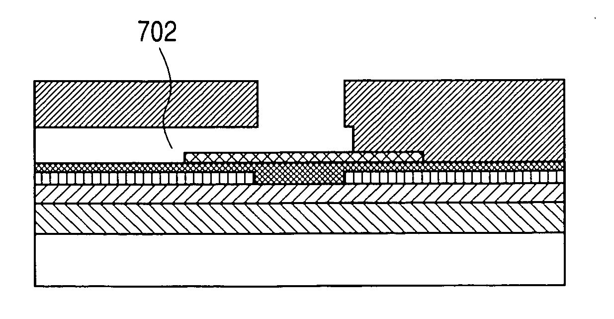
[0034]FIG. 1D shows a state in which the resist to be the shape member (the liquid flow path pattern) 800 has been removed.

[0035] In FIGS. 1A to 1D, the substrate 100 inc...
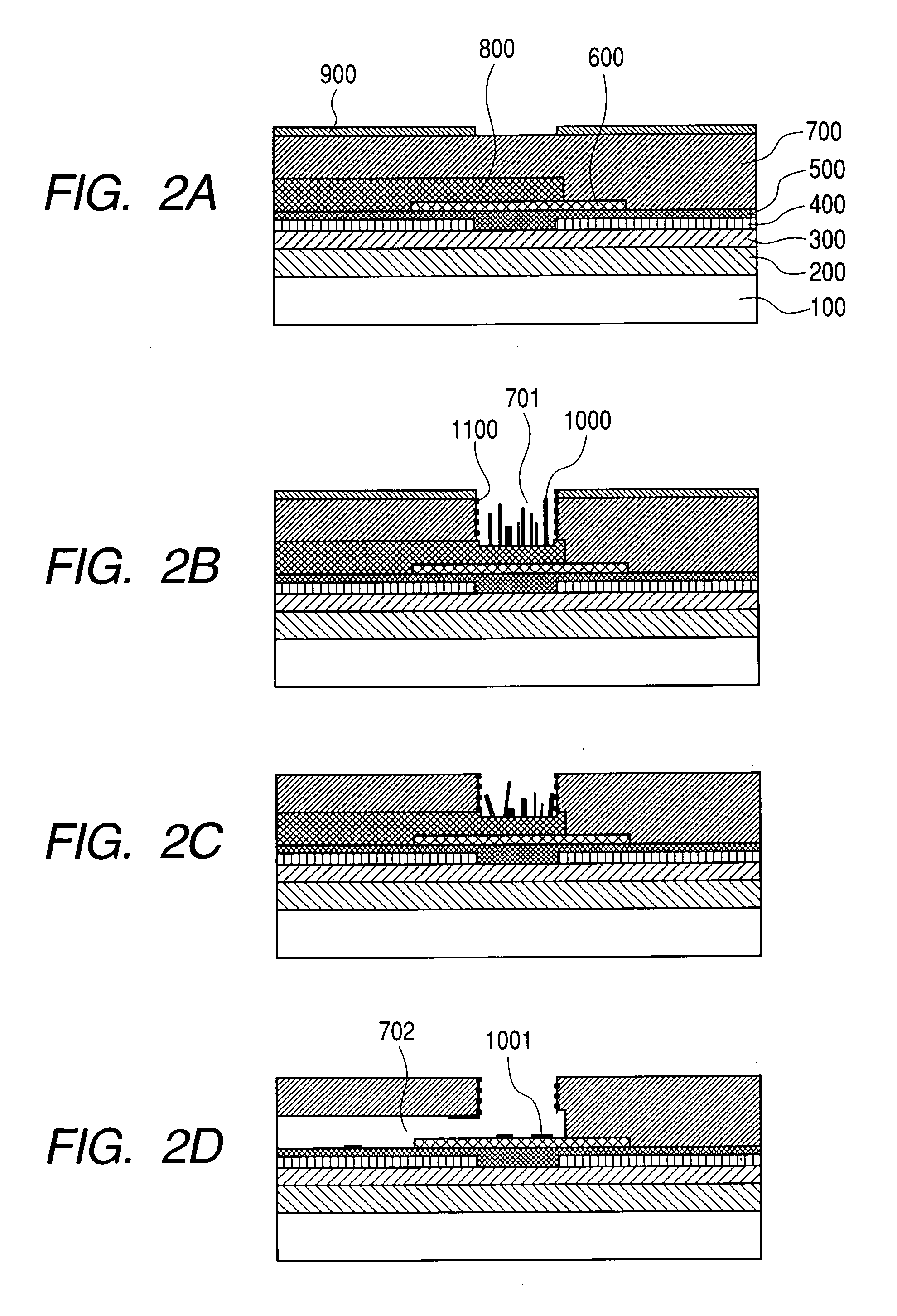
example 2

[0050] A discharge port was formed under the same conditions as those of Example 1. Incidentally, the liquid flow constituting members on an electrode pad, on a cutting line, and on the periphery of the wafer where no patterns were formed were removed not by the exposure and development process, but by dry etching similar to that of the discharge port.

[0051] For performing a discharge test, the substrate, in which the discharge port had been thus formed (in the same state as that shown in FIG. 1D), was connected to a container storing the discharging ink, i.e. the ink including pure water, diethylene glycol, isopropyl alcohol, lithium acetate and black dye food black 2 at a ratio of 79.4, 15, 3, 0.1 and 2.5, with a tube put between them. When a rectangular voltage having a peak voltage of 30 V and a frequency of 3 kHz was applied to the electrothermal conversion body for 10 μs, liquid was discharged from the orifice according to the applied signal, and flying droplets were stably f...

example 3

[0054] A discharge port was formed by changing the resin of the flow path constituting member as follows from that of Example 2. That is to say, a copolymer of glycidyl methacrylate and methyl methacrylate at a rate of 20 to 80 was used. A material produced by mixing 94% of the resin, 2% of triethylenetetramine as a curing agent and 4% of A-187 (trade name) made by Nippon Unicar Co., Ltd. was dissolved in chlorobenzene at the density of 20 wt % to be used. The resin was coated by a spinner, and the resin was baked at 80° C. for two hours as it was to be cured.

[0055] For performing a discharge test, the substrate, in which the discharge port had been thus formed (in the same state as that shown in FIG. 1D), was connected to a container storing the discharging ink, i.e. the ink including pure water, diethylene glycol, isopropyl alcohol, lithium acetate and black dye food black 2 at a ratio of 79.4, 15, 3, 0.1 and 2.5, with a tube put between them. When a rectangular voltage having a ...


PUM

PropertyMeasurementUnit
thicknessaaaaaaaaaa
thicknessaaaaaaaaaa
thicknessaaaaaaaaaa

Abstract

A manufacturing method of an ink jet recording head including a discharge port for discharging ink includes the step of forming the discharge port by performing dry etching of a discharge port forming member for forming the discharge port, wherein the discharge port forming member is formed of a Si including resin, and the step of dry etching is performed by using an etching gas including oxygen and chlorine as necessary components.

Description

BACKGROUND OF THE INVENTION [0001] 1. Field of the Invention [0002] The present invention relates to a manufacturing method of an ink jet recording head, and to an ink jet recording head manufactured by the manufacturing method. In particular, the present invention relates to a manufacturing method of an ink jet recording head equipped with an orifice plate made of a resin including silicon, and to an ink jet recording head manufactured by the manufacturing method. [0003] 2. Related Background Art [0004] An ink jet recording head applied to an ink jet printing system is generally equipped with a discharge port (orifice) of a fine liquid (ink), a liquid flow path and a liquid (ink) discharge pressure generation portion formed in a part of the liquid flow path. [0005] Various methods have conventionally been proposed as a method for producing such an ink jet recording head as a fine structure like this. [0006] Among them, there is a method which the present assignee has disclosed in J...

Claims


Application Information

Patent Timeline
Patent Type & Authority Applications(United States)
IPC IPC(8): B41J2/16B41J2/135
CPCB41J2/14129B41J2/1603Y10T29/49155Y10T29/49083Y10T29/42B41J2/1628B41J2/16
Inventor TERUI, MAKOTO
Owner CANON KK
Why Eureka
Try Eureka