Multiple-input multiple-output transmission system

a transmission system and multi-input technology, applied in the direction of orthogonal multiplex, channel coding adaptation, site diversity, etc., can solve the problems of increasing the cost of transmission equipment, so as to increase the re-transmission efficiency

Inactive Publication Date: 2006-06-01
FUJITSU LTD
View PDF7 Cites 102 Cited by
  • Summary
  • Abstract
  • Description
  • Claims
  • Application Information

AI Technical Summary

Benefits of technology

[0026] Means for deciding the transmit antenna of the transmit station or receive station decides the re-transmission transmit antenna in the following manner, by way of example: The transmit antenna deciding means ranks transmit antennas in order of descending superiority of the states of the propagation paths and, when a substream requiring re-transmission is to be re-transmitted, performs reallocation of the transmit antennas in an order that is the reverse of the order of ranking in such a manner that a data stream requiring re-transmission transmitted the previous time from a transmit

Problems solved by technology

Generally, in a MIMO system, a transmission error tends to occur in a data stream that has been transmitted from an antenna for which the state of propagation path is inferior to other transmit antennas.
Since the antenna for which the state of the propagation path is poor changes owing to fading fluctuation, the data stream that gives rise to the transmission error also changes with time.
Further, in a MIMO system, transmission error tends to occur also in a case where the correlation between antennas increases owing to the propagation environment.
Since the state of the propagation path changes in a complex manner, there are instances where a transmission error tends to occur in a specific data stream owing to an increase in correlation between sp

Method used


Image

  • Multiple-input multiple-output transmission system
  • Multiple-input multiple-output transmission system
  • Multiple-input multiple-output transmission system

Examples


first embodiment

Operation of First Embodiment

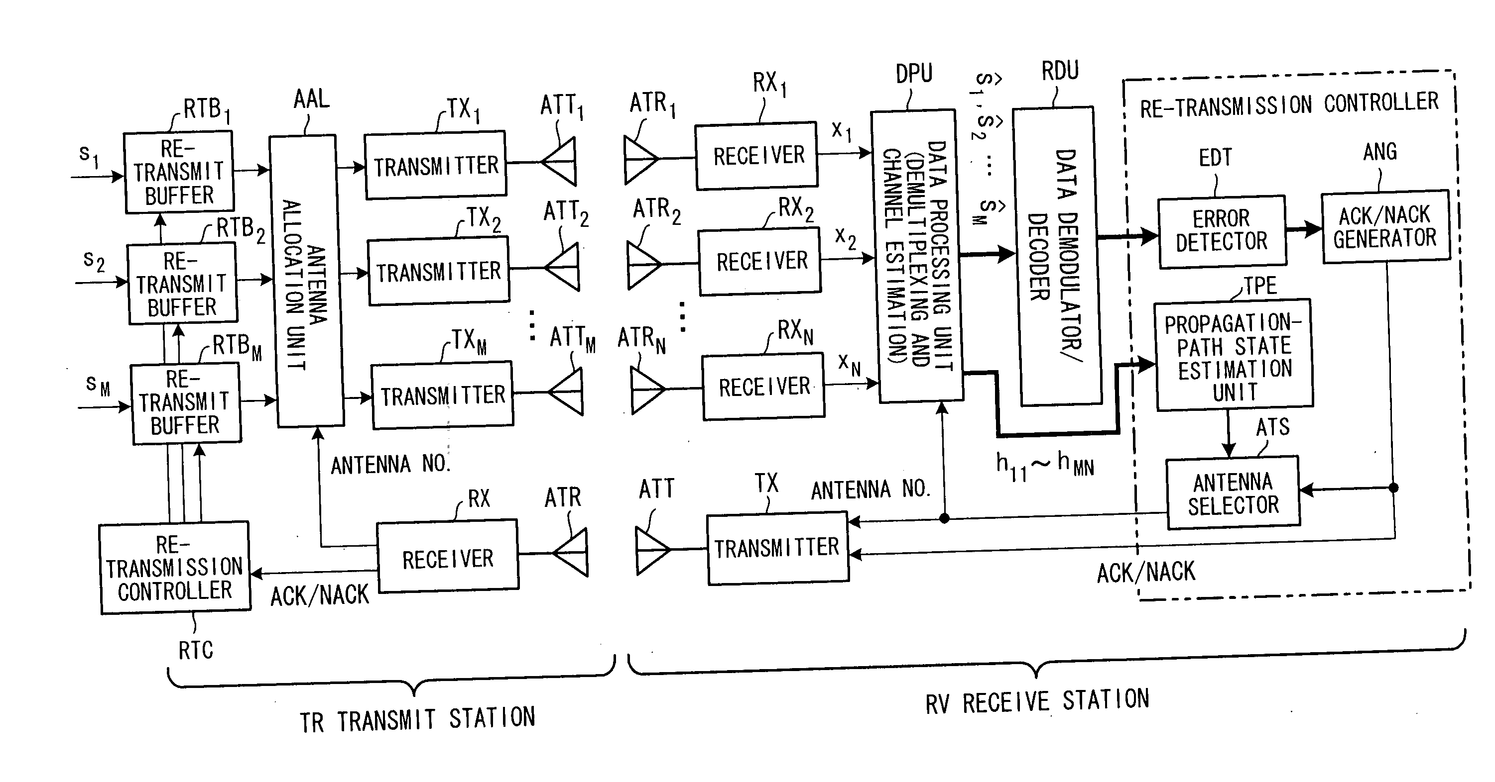
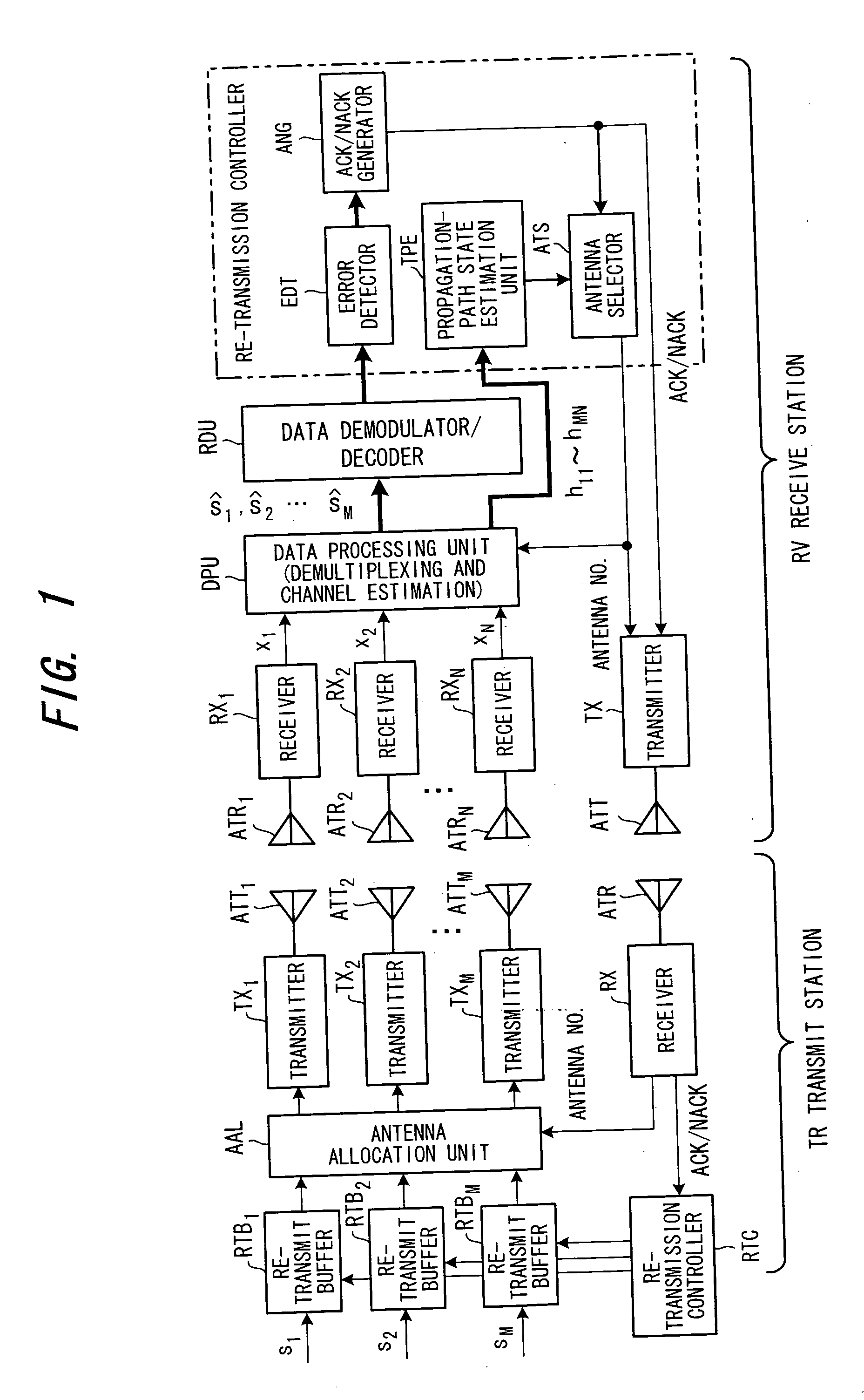
[0046] In the receive station RV, the data processing unit DPU estimates the channels h11 to hMN using pilot symbols and executes MIMO channel demultiplexing processing. When channel estimation is performed, the data processing unit DPU demodulates the pilot symbol and compares the phase and amplitude of the demodulated pilot symbol with the phase and amplitude of an already known pilot symbol to thereby estimate the characteristic A·exp(jφ) of the channels h11 to hMN. Since the pilot symbols transmitted from each of the transmit antennas are orthogonal, the data processing unit DPU is capable of estimating the channels h11 to hMN.

[0047] Further, when channel demultiplexing in a MIMO system is performed, the data processing unit DPU uses a method such as ZF, MMSE, BLAST or MLD mentioned above. The error detector EDT performs error detection for every demultiplexed data stream ŝ1, ŝ2, . . . ŝM by a method such as CRC check, and the ACK / NACK generator ANG...

second embodiment

Operation of Second Embodiment

[0062] In the receive station RV, the data processing unit DPU estimates the channels h11 to hMN using pilot symbols and executes MIMO channel demultiplexing processing (data-stream demultiplexing processing) in a manner similar to that of the first embodiment. The error detector EDT performs error detection for every demultiplexed data stream ŝ1, ŝ2, . . . ŝM by a method such as CRC check, and the ACK / NACK generator ANG reports the result (ACK / NACK) of error detection on a per-data-stream basis to the transmit station by the control channel using the oppositely directed radio link (transmitter TX, transmit antenna ATT, receive antenna ATR, receiver RX). The propagation-path estimation unit TPE estimates the state (reception power S or SIR) of the propagation path of every transmit antenna using the channel estimation results h11 to hMN and, together with the ACK / NACK information, reports this to the transmit station by the control channel using the opp...

third embodiment

(C) Third Embodiment

[0066]FIG. 7 is a diagram illustrating the structure of a receiver according to a third embodiment. This embodiment differs from the second embodiment in that a re-transmission combiner RTC is provided. It should be noted that although the transmit station is not illustrated, it has a structure identical with that of the second embodiment.

[0067] In order to improve the reception quality of the re-transmission signal, the re-transmission combiner RTC combines the re-transmission packet and a packet transmitted previously and for which NACK was detected. That is, an error-containing packet for which reception has failed and a re-transmission request (NACK information) been issued is stored in a re-transmission combining buffer by the re-transmission combiner RTCB. When a packet (data stream) that has been re-transmitted is received, the re-transmission combiner RTCB combines the re-transmission packet and the packet (data stream) inside the buffer. By thus combini...


PUM


Abstract

In a multiple-input multiple-output transmission system (MIMO system), a receive station detects whether or not there is an error in each data stream, estimates the state of the propagation path of each transmit antenna and reports, to the transmitting side, re-transmission necessary/unnecessary information, for every data stream, created based upon whether or not there is an error, and the state of the propagation path of each transmit antenna. A transmit station decides a transmit antenna that transmits a data stream requiring re-transmission, based upon the reported state of the propagation path of each transmit antenna, and re-transmits the data stream requiring re-transmission from the transmit antenna decided.

Description

CROSS-REFERENCE TO RELATED APPLICATION [0001] This application is a continuation of International Application PCT / JP03 / 08297, filed on Jun. 30, 2003, pending at the time of filing of this continuation application, the contents of which are herein wholly incorporated by reference.BACKGROUND OF THE INVENTION [0002] This invention relates to a transmission system having a multiple-input multiple-output (MIMO) architecture. More particularly, the invention relates to a multiple-input multiple-output transmission system, which has a plurality of transmit antennas and receive antennas and is capable of high-speed data transmission, and to a transmit station and receive station in this system. [0003] Of special interest in present-day wireless communication systems is a spatial multiplex transmission technique in which transmission capacity is increased in proportion to the number of transmit antennas by transmitting different data streams in parallel from different transmit antennas. Diff...

Claims


Application Information

Patent Timeline
IPC IPC(8): H04J11/00H04B7/024H04B7/0413H04B7/06H04B7/08H04L1/00H04L1/06H04L1/16H04L1/18
CPCH04B7/02H04B7/061H04B7/0691H04L1/0003H04L1/0009H04L1/06H04L1/0618H04L1/08H04L1/1607H04L1/18H04L1/1835H04L1/1874H04L1/1893H04B7/024H04B7/0413
Inventor SEKI, HIROYUKITANAKA, YOSHINORIJITSUKAWA, DAISUKE
Owner FUJITSU LTD
Why Eureka
Try Eureka