Data transfer system, data transfer method, and image apparatus system

a data transfer system and data transfer technology, applied in the field of data transfer technology, can solve the problems of deteriorating transfer efficiency, difficult to keep scalable bus widths in these interfaces, and insufficient transfer rate of pci bus for use in high-speed/high-quality image apparatuses, so as to achieve the effect of reducing the number of switches through which a data transfer route passes, avoiding the storage of an output port of a switch, and increasing the speed of data transfer

Inactive Publication Date: 2006-06-01
RICOH KK
View PDF8 Cites 57 Cited by
  • Summary
  • Abstract
  • Description
  • Claims
  • Application Information

AI Technical Summary

Benefits of technology

[0016] An object of the present invention is to improve the data transfer efficiency by avoiding contention for a port and by avoiding using a data transfer route that passes through more than necessary number of switches.
[0027] According to the above-mentioned present invention, by providing the plural upper ports in each end points and selecting an upper port according to an operation mode, the tree structure can be dynamically changed. Therefore, even when plural independent data transfers are processed in parallel, contention in data transfer routes can be avoided by keeping independent data transfer routes. In addition, a data transfer route that passes through more than necessary number of switches can be avoided. Therefore, the data transfer efficiency can be improved.
[0047] According to the above-mentioned present invention, by providing the plural end points in each device and determining an end point according to an operation mode, the tree structure can be dynamically changed. Therefore, even when plural independent data transfers are processed in parallel, contention in data transfer routes can be avoided by keeping independent data transfer routes. In addition, a data transfer route that passes through-more than necessary number of switches can be avoided. Therefore, the data transfer efficiency can be improved. Especially, according to the present invention, the route can be set such that it does not pass through the root of the tree structure. Thus, data communication can be performed efficiently irrespective of bandwidth of the root part. Further, even in a system in which communication bandwidth necessary between devices change according to operation status, optimum communication bandwidth can be always maintained by changing route setting.
[0052] According to the present invention, since each image apparatus is connected to a switch that is a top in a tree structure without data transfer via the root complex, the speed of the data transfer can be increased compare with a case where the data pass through the root complex. Generally, high-cost is required if all functions are included in a image apparatus. In contrast, according to the present invention, since plural image apparatuses having different performances are connected via the root complex so that the image apparatuses having different performances can communicate with each other. Therefore, even when desired image processing (for example, high-speed processing, color printing, laser printing, wide width paper printing or the like) cannot be performed by one image apparatus (for example, low-speed, black and white, inkjet printing, A3 size or the like), the desired image processing can be realized by using resources of another image apparatus. Further, by using the advanced switch, plural image apparatus systems can be connected.
[0055] According to the present invention, since the devices having the strong correlation with each other are connected to the upper side of the tree structure via the common switch, data transfer among the devices having strong correlation only passes through the common switch. Thus, contention for an output port of a switch can be avoided as much as possible, and the number of switches through which a data transfer route passes can be decreased as much as possible. Therefore, the speed of the data transfer can be further increased compared with the case where the route passes through the root complex.

Problems solved by technology

However, in the PCI bus that adopts parallel data transfer, there are problems such as racing and skew, and the transfer rate of the PCI bus is not enough for use in a high-speed / high-quality image apparatus.
In addition, there is a problem in that it is difficult to keep scalable bus widths in these interfaces.
However, since the communication route is fixed when simply using the PCI Express system, contention for a data transfer route may occur so that transfer efficiency deteriorates when plural independent data transfers are processed in parallel.
Thus, the change of connections is not a substantial solution.
Such deterioration of the data transfer rate occurs not only when the contention for a data transfer route occurs but also when the data transfer route passes through more than necessary number of switches.
In addition, since the data transfer route is statically determined, there is no software solution means when a bottleneck occurs.
In addition, when a route that passes through the root complex of the tree structure is used for data transfer between devices, speed of the data transfer may be decreased, so that, in such a case, it is difficult to say that the function of the PCI Express is fully utilized.
More particularly, when the route that passes through the root complex is used in data transfer, contention is likely to occur at an output port in a switch existing between the device and the root complex, so that the transfer rate is decreased.
As mentioned before, such deterioration of the data transfer rate occurs not only when the contention for a data transfer route occurs but also when the data transfer route passes through more than necessary number of switches.
At this viewpoint, when adopting a configuration in which the route that passes through the root complex is used, cases where a data transfer route passes through multiple number of switches may increase so that there is a risk in that the data transfer rate decreases.
But, if all functions are included in a single image apparatus, the cost becomes high, and the image apparatus may include many useless functions since the high-speed and high performance functions are not always used.

Method used


Image

  • Data transfer system, data transfer method, and image apparatus system
  • Data transfer system, data transfer method, and image apparatus system
  • Data transfer system, data transfer method, and image apparatus system

Examples


first embodiment

[0185] A first embodiment of the present invention is described first.

[0186] [Data Transfer System, Image Forming System]

[0187] The data transfer system of the present embodiment uses the before-mentioned PCI Express system, in which especially the tree structure is expanded and improved.

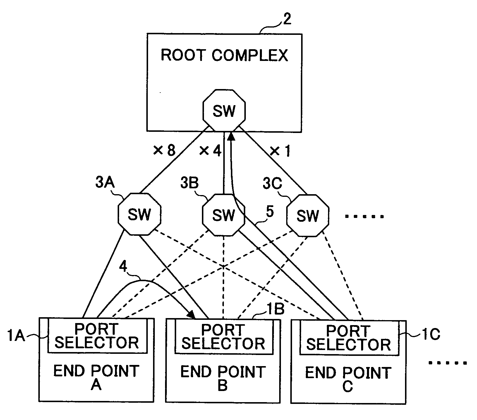
[0188]FIG. 18 shows a principle schematic diagram of an example of the tree structure of the data transfer system of the present embodiment. According to the specification of the before-mentioned PCI Express system, the upper port of the end point is only one. But, according to the present embodiment, each of end points A, B, C, . . . has plural upper ports, and each of the end points A, B, C, . . . has a port selector (port selection part) (1A,1B,1C, . . . ) for selecting an upper port to be used according to an operation mode of the data transfer system.

[0189] Therefore, in the tree structure of the data transfer system of the present embodiment, a root complex 2 for managing the whole structur...

second embodiment

[0217] In the following, a second embodiment of the present invention is described.

[0218] [Data Transfer System, Image Forming System]

[0219] The data transfer system of the present embodiment uses the before-mentioned PCI Express system, in which especially the tree structure is expanded and improved.

[0220]FIG. 31 shows a principle schematic diagram of an example of the tree structure of the data transfer system of the present embodiment. According to the specification of the before-mentioned PCI Express system, each of devices that exists in the lower side (end side) of the tree structure includes one end point. On the other hand, according to the present embodiment, plural end points (A1, A2, . . . , A4, B1, . . . , B4, C1, . . . , C4, D1, . . . , D4, . . . ) are assigned to each of the devices A, B, C, D, . . . , so that each end point is connected to a lower side port of a corresponding upper side switch. In addition, arbiters 2A, 2B, 2C, 2D, . . . are provided in correspondin...

third embodiment

[0253] In the following, third embodiment of the present invention is described.

[0254] [Image System]

[0255] The image system of the present embodiment uses the before-mentioned PCI Express system, in which especially the tree structure is improved.

[0256]FIG. 37 shows a principle schematic diagram of an example of the tree structure of the image system of the present embodiment. The present embodiment includes image apparatuses 1 and 2 having different structures (performance). The image system has a tree structure in which switches 3 and 4 in the PCI Express system exist at the top, and plural devices included in the image apparatuses 1 and 2 exist at end point positions and are connected to the switches 3 and 4. The image apparatus 1 is a high-speed image apparatus, for example. The image apparatus 1 includes a control part 5a, an input part 5b, an output part 5c, a storage 5d, a switch 5e, an image process part 5f, a compressor 5g, an expandor 5h, a data converter 5i, a rotator ...


PUM


Abstract

A data transfer system using a high-speed serial interface system that forms a tree structure in which point-to-point communication channels are established for data sending and data receiving independently is provided. The data transfer system includes plural end points each having plural upper ports each of which is connected to a switch of an upper side, wherein each end point includes a port selecting part for selecting a port to be used according to an operation mode of the data transfer system so as to dynamically change the tree structure.

Description

BACKGROUND OF THE INVENTION [0001] 1. Field of the Invention [0002] The present invention relates to a data transfer technology, and relates to an image system such as a compound machine (also to be referred to as MFP). [0003] 2. Description of the Related Art [0004] Generally, apparatuses and systems that deal with image data and other data use a PCI bus as an interface between devices. However, in the PCI bus that adopts parallel data transfer, there are problems such as racing and skew, and the transfer rate of the PCI bus is not enough for use in a high-speed / high-quality image apparatus. Recently, instead of the parallel interface such as the PCI bus, use of a high-speed serial interface is being studied. As widely used serial interfaces, IEEE1394, USB and the like are previously known. However, the transfer rate of these interfaces are less than the PCI. In addition, there is a problem in that it is difficult to keep scalable bus widths in these interfaces. Thus, as another hi...

Claims


Application Information

Patent Timeline
Patent Type & Authority Applications(United States)
IPC IPC(8): H04L12/56
CPCH04L45/02H04L45/48
Inventor IKEDA, JUNICHIOSHIKIRI, KOJIOIZUMI, ATSUHIROMAITA, YUTAKANUMAKURA, SATORUTERAO, NORIYUKISHINDOH, YASUYUKISASAKI, TOHRUTAKEO, KOJI
Owner RICOH KK
Why Eureka
Try Eureka