
Protection of thermal barrier coating by an impermeable barrier coating

a technology of impermeable barrier and thermal barrier coating, which is applied in the direction of superimposed coating process, machine/engine, natural mineral layered products, etc., can solve the problems of insufficient mechanical properties, insufficient mechanical properties, and inability to retain base alloys alone. to achieve the effect of preventing infiltration of contaminant composition

Active Publication Date: 2006-06-01
GENERAL ELECTRIC CO
View PDF21 Cites 39 Cited by
  • Summary
  • Abstract
  • Description
  • Claims
  • Application Information

AI Technical Summary

Benefits of technology

"The invention relates to a method for protecting thermal barrier coatings on metallic parts from contamination. The method involves depositing a layer of rare earth silicate on the thermal barrier coating to prevent the contaminant from infiltrating and damaging the coating. This results in better protection of the thermal barrier coating and improved performance of the metallic part in high-temperature environments."

Problems solved by technology

However, as operating temperatures increase, the high temperature durability of the components within the engine must correspondingly increase.
When exposed to the demanding conditions of gas turbine engine operation, particularly in the turbine section, the base alloy alone may be susceptible to damage, such as oxidation and corrosion attack, and may not retain adequate mechanical properties.
Under service conditions, thermal barrier coated engine parts can also be susceptible to various modes of damage, including erosion, oxidation, and attack from environmental contaminants.
At temperatures of engine operation, adherence of these environmental contaminants on the hot thermal barrier coated surface can cause damage to the thermal barrier coating.
Molten contaminant compositions can dissolve the thermal barrier coating or can infiltrate its pores and openings, initiating and propagating cracks causing delamination and loss of thermal barrier coating material.
Damage to thermal barrier coatings occurs when the molten CMAS infiltrates the thermal barrier coating.
The stress build up in the thermal barrier coating may cause cracking and / or spallation of the coating material and loss of the thermal protection that it provides to the underlying part.
Alternately or in addition, the CMAS can react chemically with the TBC to accelerate thermal sintering or dissolve stabilizing components such as Y2O3 resulting in damage to the TBC coating.

Method used


Image

  • Protection of thermal barrier coating by an impermeable barrier coating
  • Protection of thermal barrier coating by an impermeable barrier coating
  • Protection of thermal barrier coating by an impermeable barrier coating

Examples


example

[0043] To evaluate the potential for using an impermeable barrier coating, Sc2SiO5 material was hot pressed and sintered into a free standing ceramic pellet. The Sc2SiO5 was tested in thermal exposure at about 1315° F. (2400° C.) (FIG. 4) for about 50 hours with ˜80 mg / in2 CMAS overlaying the surface.

[0044] This Sc2SiO5 material was then compared with free standing 9.5 wt % yttria stabilized zirconia (YSZ) samples. Shown in FIG. 5 and FIG. 6 are the thermal exposure attack of the YSZ samples at about 1232° F. (2250° C.) for about 16 hours with ˜80 mg / in2 CMAS overlaying the surface and 1343° C. (2450° F.) for about 16 hours with ˜80 mg / in2 CMAS overlaying the surface. As can be seen from a comparison of the figures, this example advantageously demonstrates the lack of material loss for the Sc2SiO5 sample demonstrating the strong resistance to environmental attack as compared with YSZ.


PUM

PropertyMeasurementUnit
thicknessaaaaaaaaaa
thicknessaaaaaaaaaa
operating temperaturesaaaaaaaaaa

Abstract

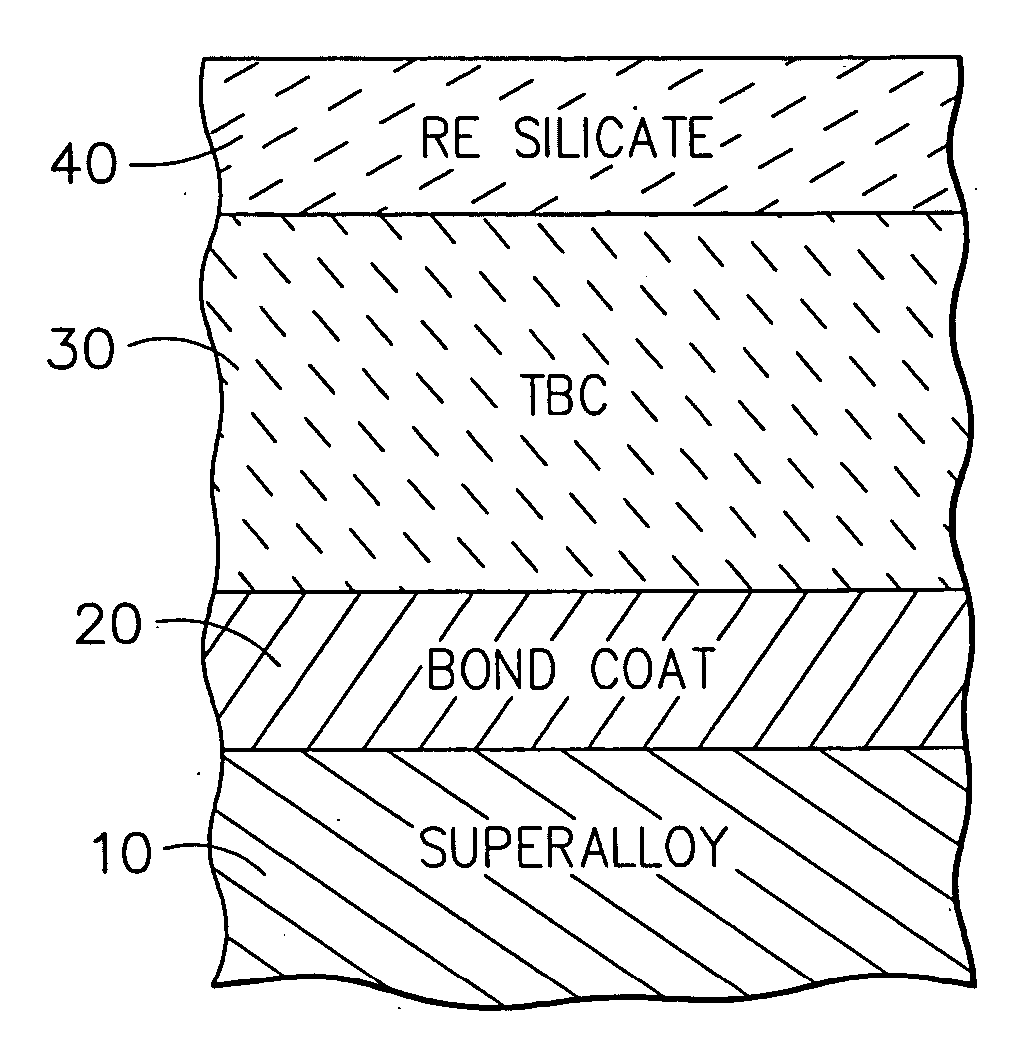
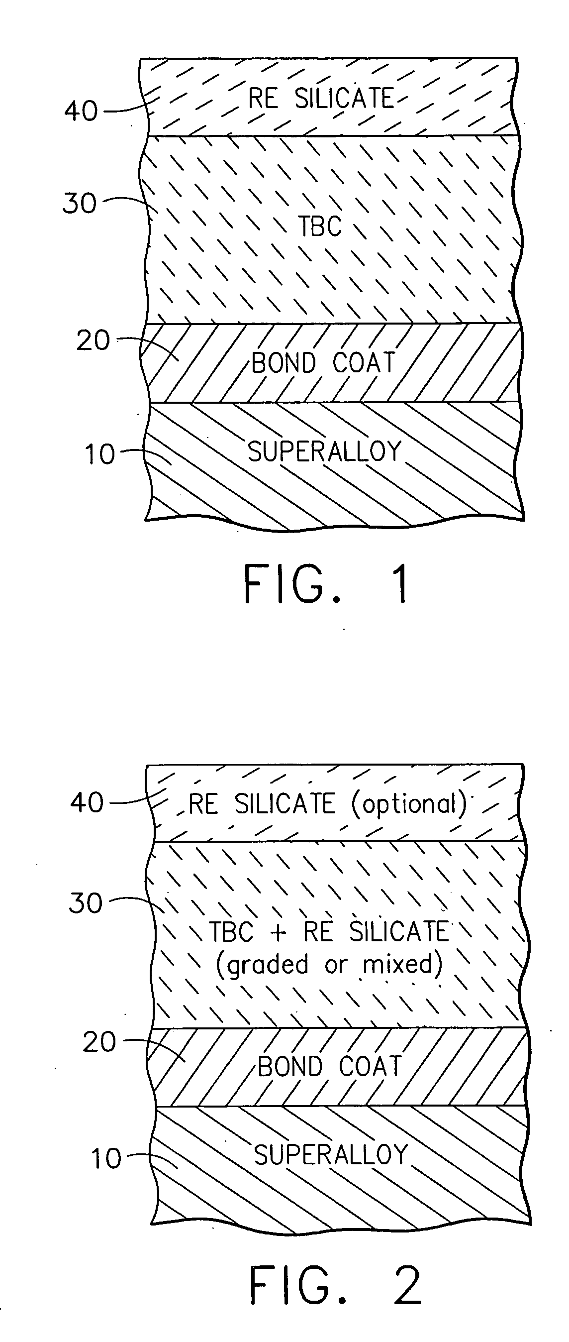
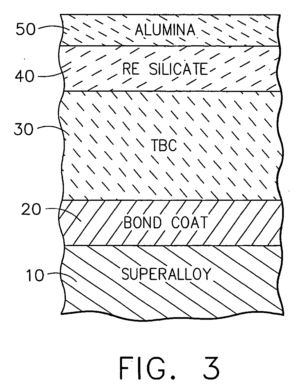
According to an embodiment of the invention, disclosed is a composite comprising a porous thermal barrier coating on a metallic part and an impermeable barrier coating adjacent to the outer surface of the thermal barrier coating. The impermeable barrier coating is dense and non-porous and comprises a rare earth silicate, the impermeable barrier coating thereby preventing infiltration of the contaminant composition into the thermal barrier coating.

Description

GOVERNMENT RIGHTS [0001] The invention was made in part under contract number N00019-96-C-1076 awarded by the Government (Navy). Accordingly, the Government has certain rights in this invention.CROSS-REFERENCE TO RELATED APPLICATION [0002] The subject application shares certain attributes with U.S. Ser. No., entitled, Protection of Thermal Barrier Coating By A Sacrificial Coating, which is filed concurrently herewith. The contents of this application are hereby incorporated by reference. FIELD OF THE INVENTION [0003] The invention generally relates to a method for protecting thermal barrier coatings deposited on gas turbine and other heat engine parts from the deleterious effects of environmental contaminants. More particularly, the invention relates to a method of using an impermeable coating, where the impermeable coating reduces infiltration of liquid contaminant compositions into the thermal barrier coating, as well as articles coated with the impermeable coating. BACKGROUND OF ...

Claims


Application Information

Patent Timeline
Patent Type & Authority Applications(United States)
IPC IPC(8): B32B15/04B32B9/00
CPCF05B2230/90F05C2253/12Y02T50/67C23C28/321C23C28/325Y10T428/263C23C28/345C23C28/3455C23C28/36Y10T428/12611C23C28/3215Y10T428/249953Y10T428/31678Y02T50/60
Inventor HAZEL, BRIAN THOMASSPITSBERG, IRENEGOVERN, CHRISTINENAGARAJ, BANGALORE A.
Owner GENERAL ELECTRIC CO
Learn More