Holder plate supporting grinding elements

a technology of holder plate and supporting rod, which is applied in the direction of gear teeth, manufacturing tools, manufacturing apparatus for gear teeth, etc., can solve the problems of cracking, crushing or breaking of the holder plate, and achieve the effect of improving the scraping

Inactive Publication Date: 2006-06-01
HTC SWEDEN AB
View PDF9 Cites 12 Cited by
  • Summary
  • Abstract
  • Description
  • Claims
  • Application Information

AI Technical Summary

Benefits of technology

[0013] By arranging the grinding element in accordance with the invention, a reduced sensitivity is achieved to removed material located on the floor surface since the grinding element has a smaller area affected by such removed material. By arranging the grinding element with its longitudinal direction parallel to the tangent, the holder plate itself is made stiffer, reducing the risk of this falling away from the grinding plate when such assembly elements as shown in PCT / SE2004 / 000905 are used. Also a more even flow of coolant is achieved in applications where coolant is utilised.
[0014] The base surface can taper in a first direction parallel to the tangent. By tapering the base surface in the direction of the tangent, a plough effect is achieved which means that removed material located on the floor surface is eliminated, hence reducing the force which this exerts on the grinding element.
[0016] According to one embodiment the base surface at its one end in the longitudinal direction has a tip pointing in the longitudinal direction. Because the base surface has a tip, an improved scraping effect is achieved which is advantageous when for example paint residue or similar remains on and should be removed from the floor surface.
[0017] According to another embodiment the base surface is rounded at its one end in the longitudinal direction. Because the base surface is rounded there is less risk that scratches will occur on the floor surface.

Problems solved by technology

One problem with known holder plates for grinding elements is that unevenness and protrusions on the floor surface and removed material located on the floor surface cause varying and sometimes great stresses on the grinding element which can lead to its cracking, crushing or breaking from the holder plate.

Method used


Image

  • Holder plate supporting grinding elements
  • Holder plate supporting grinding elements
  • Holder plate supporting grinding elements

Examples


Embodiment Construction

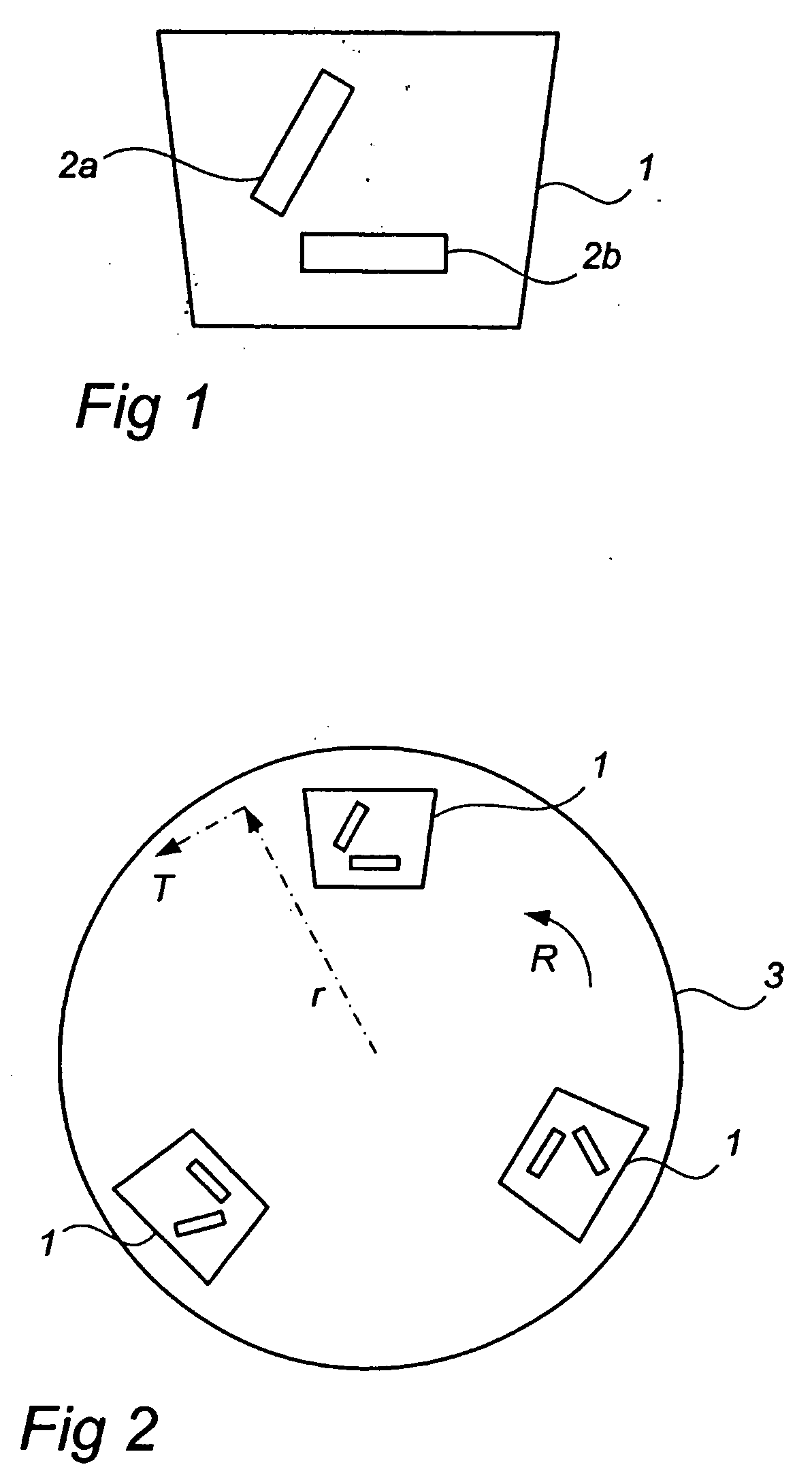
[0024]FIG. 1 shows a known holder plate 1 supporting grinding elements which is fitted with two grinding elements 2a, 2b arranged in the traditional manner.

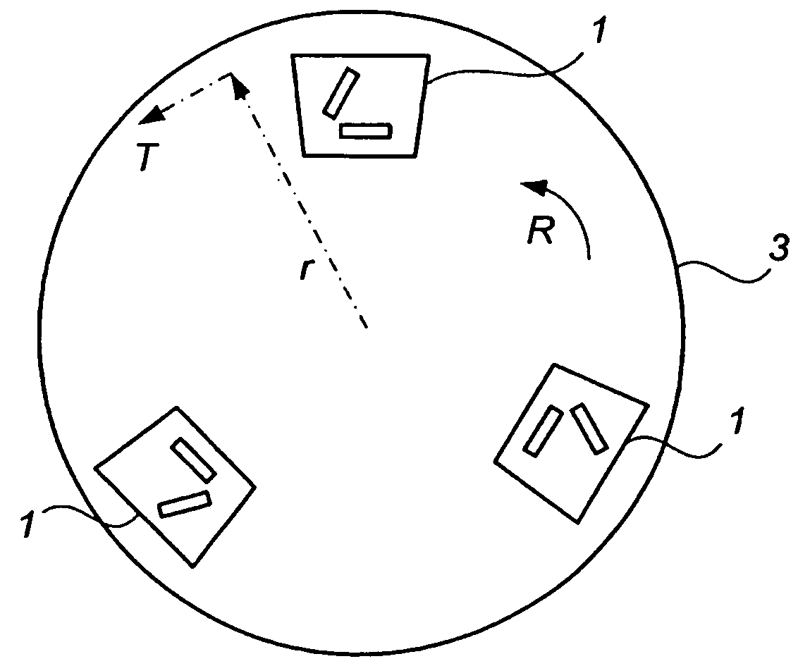
[0025]FIG. 2 shows a known grinding plate 3 on which are arranged three holder plates 1 supporting grinding elements. It can be seen that the number of holder plates 1 arranged on the grinding plate can vary as required. Normal configurations comprise 3-6 holder plates 1.

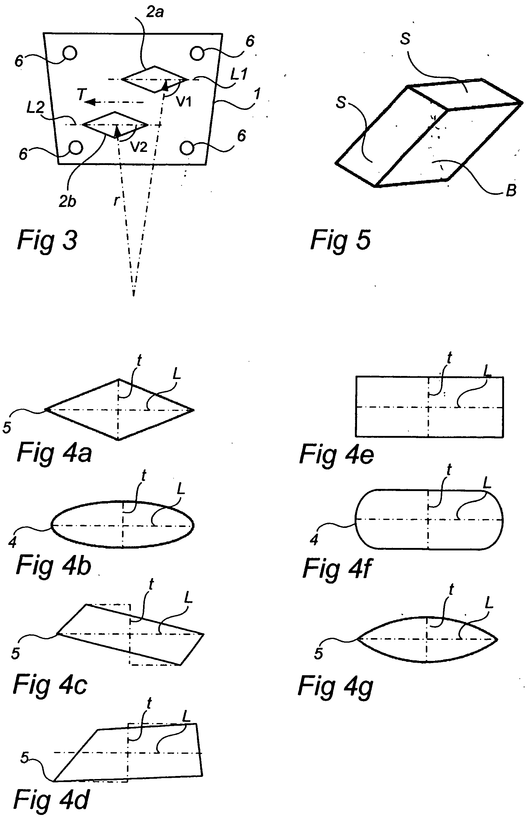
[0026]FIG. 3 shows a holder plate 1 supporting grinding elements according to the invention. On the holder plate 1 are arranged two grinding elements 2a, 2b in such a way that their respective longitudinal direction L is substantially parallel to a tangent on the grinding plate 3 on which the holder plate 1 is to be arranged. According to one embodiment therefore the angles V1 and V2 between the longitudinal directions L1, L2 of the respective grinding elements 2a, 2b, and the radius r of the grinding plate are essentially equally large but they can also deviat...


PUM


Abstract

A holder plate supporting grinding elements for grinding and / or polishing hard floor surfaces of stone, concrete, terrazzo or similar, has an element for mounting this on a driven grinding plate that rotates flat substantially parallel with the floor surface. The holder plate carries at least two grinding elements where each of the grinding elements has the shape of a geometric body which is defined by two substantially parallel base surfaces spaced apart from each other and at least one side surface extending between the edges of the base surface. The base surfaces are substantially parallel with the holder plate and substantially oblong. The grinding element is arranged on the holder plate so that when the holder plate is mounted on the grinding plate, a longitudinal direction of the base surface concerned is substantially parallel with a tangent on the grinding plate.

Description

TECHNICAL FIELD [0001] The present invention relates to a holder plate supporting grinding elements for grinding and / or polishing of hard floor surfaces such as stone, concrete, terrazzo or similar. BACKGROUND [0002] Holder plates supporting grinding elements are known from EP-1 321 233 or from PCT / SE2004 / 000905. A multiplicity, normally at least three, such holder plates supporting grinding elements are mounted on a driven grinding plate (FIG. 2) that rotates flat, substantially parallel with the floor surface, which plate is in turn mounted in a grinding machine of for example the type shown in W002 / 062524 or EP-0 700 327. The grinding plate with the holder plate with grinding elements mounted is thus brought into contact with the floor surface, where the grinding plate is rotated and the floor surface ground and / or polished. [0003] In applications where only grinding and / or polishing grinding elements are used, normally at least two circular or rectangular grinding elements are a...

Claims


Application Information

Patent Timeline
Patent Type & Authority Applications(United States)
IPC IPC(8): B23F21/03
CPCB24B7/186B24D7/06
Inventor THYSELL, HAKAN
Owner HTC SWEDEN AB
Why Eureka
Try Eureka