

Indwelling implant for embolization
- Summary
- Abstract
- Description
- Claims
- Application Information
AI Technical Summary
Benefits of technology
Problems solved by technology
Method used
Image

Examples
embodiments
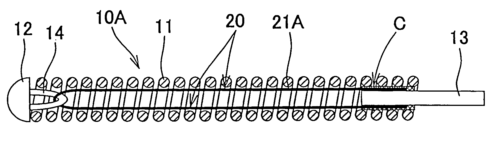
[0024]FIG. 1 is an explanatory cross-sectional view illustrating schematically the configuration representing an example of the indwelling implant for embolization in accordance with the present invention.
[0025] This indwelling implant for embolization (simply referred to hereinbelow as “indwelling implant”) 10A comprises a metal coil 11 which is preferably flexible. A semispherical rounded head portion 12 is provided in the distal end portion (left end portion in FIG. 1) of the metal coil 11. Furthermore, for example, a rod-like joint member 13 for supporting the metal coil 11 is so provided in the base end portion of the metal coil 11 that it protrudes and extends outwardly (to the right in FIG. 1) in the axial direction of the coil from the edge of the base end of the metal coil 11 after part thereof has been fixed to the inner peripheral surface of the based end portion of metal coil 11. Further, in the indwelling implant for embolization of the present application, the semisph...
manufacturing example 1
[0057] A metal loop with an elemental wire diameter of 30 μm and a total length of 2 mm that was formed of a platinum-tungsten alloy wire material was inserted toward a proximal end into a distal end portion of a metal coil (coil diameter 250 μm, coil length 30 mm) formed from the same platinum-tungsten alloy wire material with an elemental wire diameter of 40 μm, and the coil end and the metal loop were welded by TIG welding under an argon-helium mixed gas with the object of preventing oxidation. At this time, as a result of welding the metal loop to the distal end portion of the metal coil, the semispherical rounded head portion was naturally formed at the distal end of the metal coil under the effect of surface tension of the metal. A platinum-tungsten alloy wire with an elemental wire diameter of 12 μm and a total length of 60 mm was inserted as an axial extension controlling member into the metal loop, both ends of the platinum-tungsten alloy wire were introduced between a hold...
manufacturing example 2
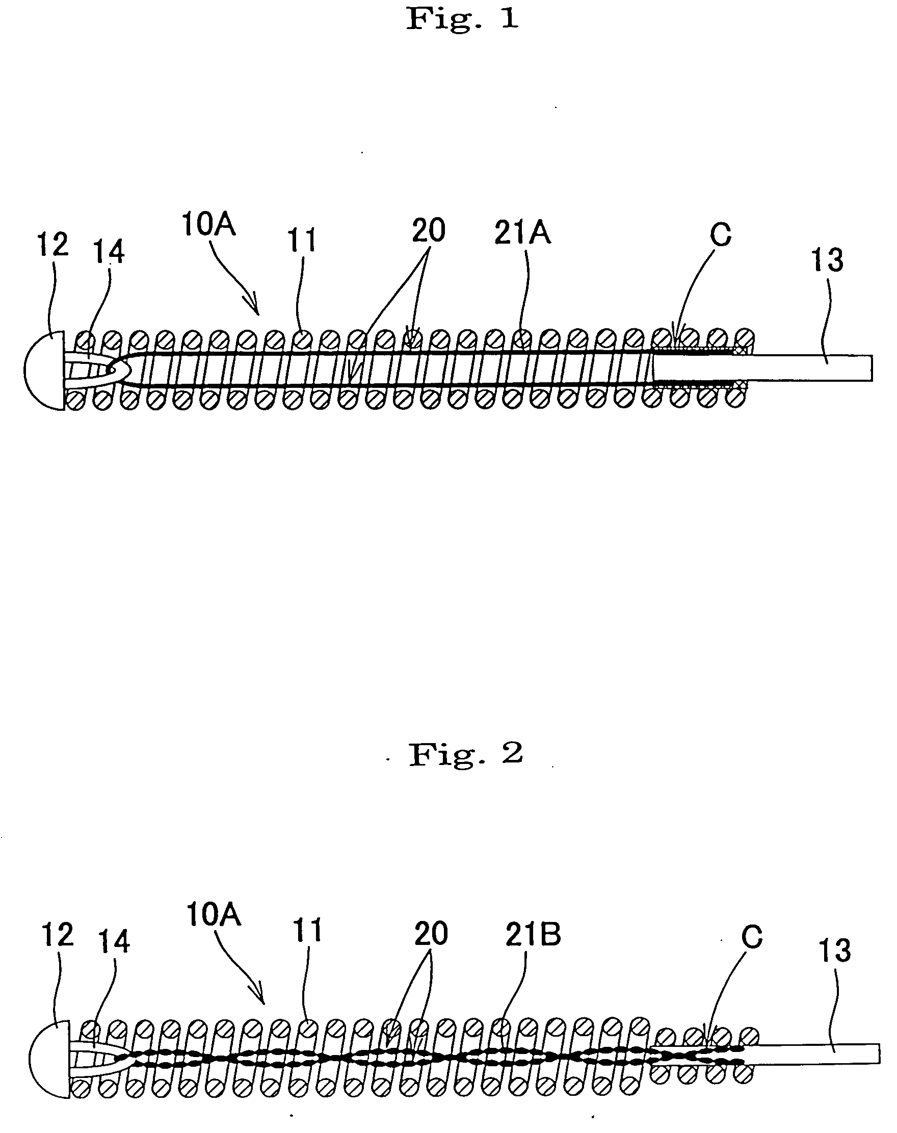
[0058] In the Manufacturing Example 1, the platinum-tungsten alloy of the materials forming the coil, metal loop and axial extension controlling member was replaced with a platinum-iridium alloy, the axial extension controlling member was composed of a twisted wire obtained by loosely twisting three platinum-iridium alloy wires with an elemental wire diameter of 7 μm and a total length of 60 mm, after the axial extension controlling member has been inserted through the metal loop, the wire was further twisted, and then both ends of the axial extension controlling member were caulked together with the joint member 13 to shrink and join them to a proximal end portion of the coil. Other features were identical to those of the Manufacturing Example 1. As a result, an indwelling implant with the configuration shown in FIG. 2 was obtained. This indwelling implant will be called “indwelling implant 2”.
PUM
 Abstract
Description
Claims
Application Information