Endoluminal stent, self-supporting endoluminal graft and methods of making same

Active Publication Date: 2006-06-01
VACTRONIX SCI LLC
View PDF99 Cites 38 Cited by
  • Summary
  • Abstract
  • Description
  • Claims
  • Application Information

AI Technical Summary

Benefits of technology

[0016] Heretofore, joints between discrete sections of endoluminal stents required welds in order to join sections of the stent. One particular advantage of the present invention is that by forming the stent using vapor deposition techniques, not only are discrete sections atomically joined without the use of welds, but different materials may be employed in different and discrete sections of the stent in order to impart distinct material properties and, therefore, functionality, to the discrete sections.
[0017] Finally, the present invention also includes a self-supporting endoluminal graft. As used herein the term Agraft@ is intended to indicate any type of tubular member that exhibits integral columnar and circumferential strength and which has openings that pass through the thickness of the tubular membe

Problems solved by technology

One of the difficulties with many conventional stent designs arises due to the conflicting criteria between the desired properties of circumferential or hoop strength of the stent, longitudinal or column strength, longitudinal flexibility, fish-scaling of individual structural members of the stent, fatigue life, corrosion resistance, corrosion fatigue, hemodynamics, radioopacity and biocompatibility and the capability of passing the stent through an already implanted stent.
Typically, stents that are designed to optimize for hoop strength typically sacrifice either column strength and/or longitudinal flexibility, while stents that are de

Method used


Image

  • Endoluminal stent, self-supporting endoluminal graft and methods of making same
  • Endoluminal stent, self-supporting endoluminal graft and methods of making same
  • Endoluminal stent, self-supporting endoluminal graft and methods of making same

Examples


Embodiment Construction

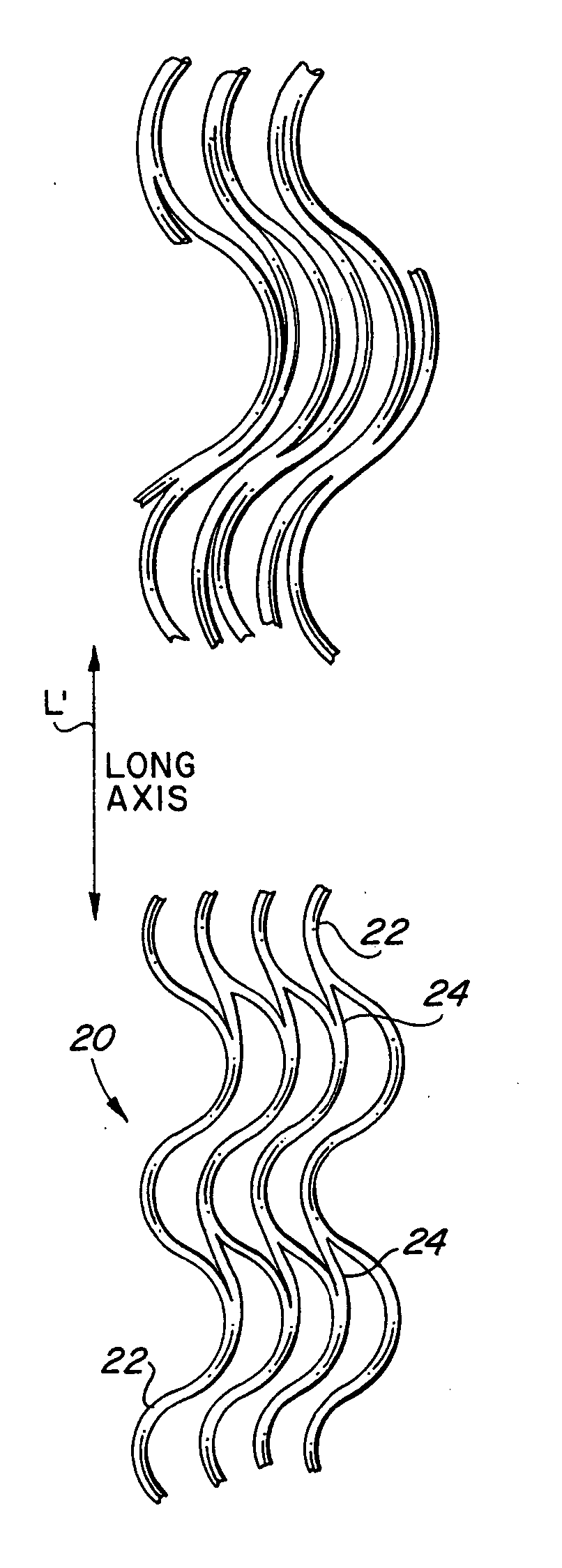
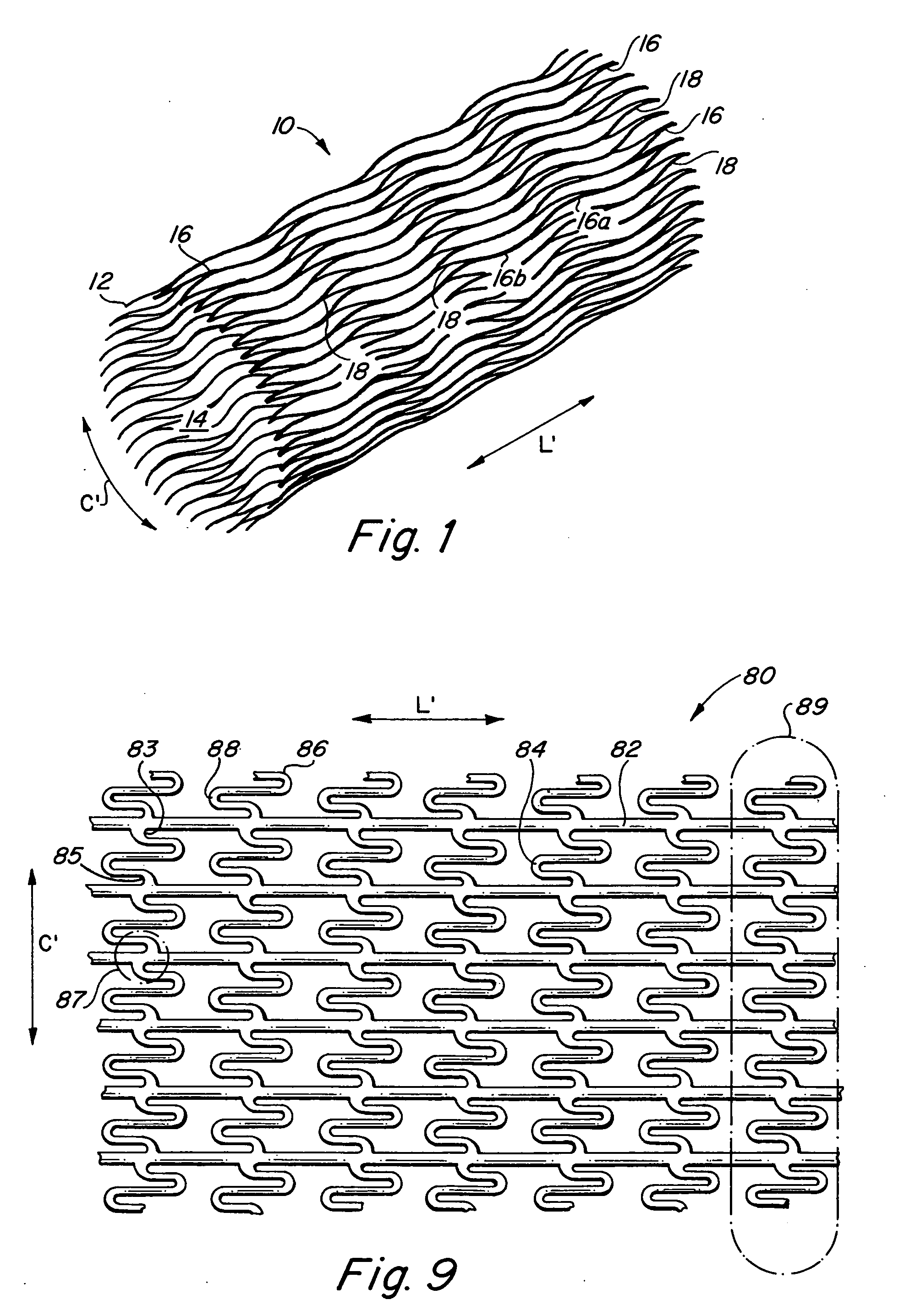
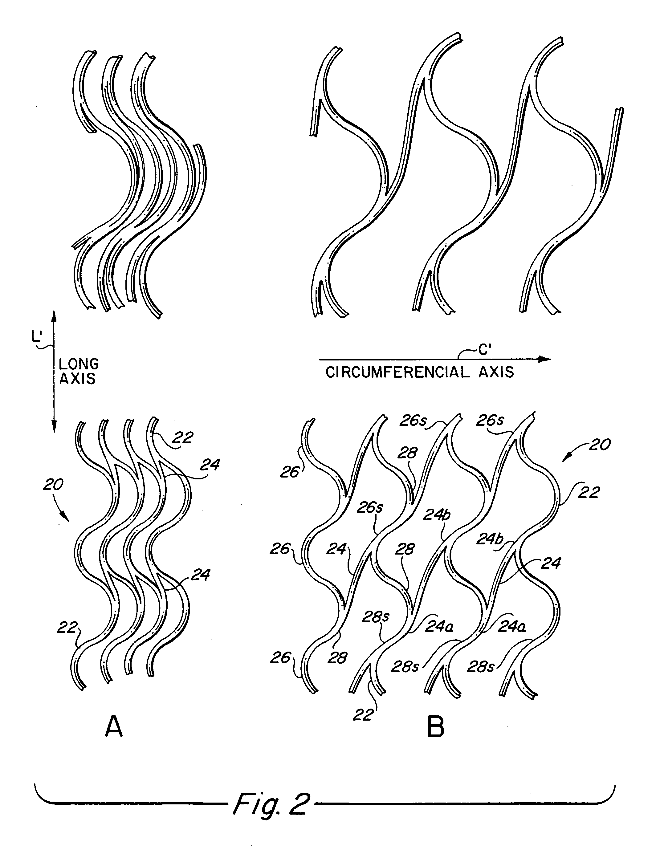
[0040] In accordance with the present invention there is provided several preferred embodiments. In each of the preferred embodiments of the present invention, the general configuration of the inventive endoluminal stent is identical. With particular reference to FIG. 1, the inventive endoluminal stent 10 consists generally of a tubular cylindrical element having a stent wall 12 that defines a central lumen 14 of the stent. A plurality of first structural elements 16 are arrayed about the circumferential axis C=of the stent 10 and extend parallel along the longitudinal axis of stent 10. A plurality of second structural elements 18 interconnects adjacent pairs of the plurality of first structural elements 16. Each of the plurality of first structural elements 16 have a generally sinusoidal configuration with a plurality of peaks 16a and a plurality of troughs 16b of each first structural element. As noted above, the plurality of peaks 16a and the plurality of troughs 16b may have eit...


PUM

PropertyMeasurementUnit
Grain sizeaaaaaaaaaa
Lengthaaaaaaaaaa
Widthaaaaaaaaaa

Abstract

An endoluminal stent composed of a plurality of first structural elements arrayed to form the circumference of the stent and extending along the longitudinal axis of the stent, and a plurality of second structural elements that interconnect adjacent pairs of first structural elements. The plurality of first structural elements have either a linear shape or a generally sinusoidal configuration with either a regular or irregular periodicity or regions of regular and regions of irregular periodicity between the peaks and troughs of the pattern, with the peaks and troughs projecting from the first structural elements in the circumferential axis. The plurality of second structural elements are generally linear or sinusoidal-shaped members which interconnect an apex of a peak of one of the plurality of first structural elements with an apex of a valley of a second and adjacent one of the plurality of first structural elements. Each of the plurality of second structural elements are generally oriented parallel to the circumferential axis of the stent.

Description

CROSS-REFERENCE TO RELATED APPLICATION [0001] This application is a divisional application and corresponds to and claims priority of U.S. utility patent application Ser. No. 09 / 707,685, filed Nov. 7, 2000 and Ser. No. 10 / 120,800, filed Apr. 11, 2002, now abandoned.BACKGROUND OF THE INVENTION [0002] The present invention relates generally to endoluminal stents and grafts designed for delivery into an anatomical passageway using minimally invasive techniques, such as percutaneous intravascular delivery using a delivery catheter passed over a guidewire. More particularly, the present invention relates to endoluminal stents having a scaffold structure and structural geometry which is particularly well-suited for providing physiologically acceptable radial or hoop strength and longitudinal flexibility, while also presenting a luminal surface thereof which presents less obstruction to longitudinal shear forces during fluid flow across the luminal surface of the inventive device while maxi...

Claims


Application Information

Patent Timeline
IPC IPC(8): A61F2/90A61F2/00A61F2/06
CPCA61F2/91A61F2220/0058A61F2002/072A61F2002/30322A61F2002/91508A61F2002/91516A61F2002/91533A61F2002/9155A61F2002/91558A61F2002/91566A61F2002/91575A61F2002/91583A61F2250/0014A61F2250/0026C23C14/0005C23C14/042C23C14/221C23C14/34A61F2210/0076A61F2/915
Inventor BAYLE, CHRISTOPHER T.BAILEY, STEVEN R.PALMAZ, JULIO C.BANAS, CHRISTOPHER E.
Owner VACTRONIX SCI LLC
Why Eureka
Try Eureka