Optimized land mobile satellite configuration and steering method

a satellite configuration and satellite technology, applied in the direction of navigation instruments instruments for comonautical navigation, etc., can solve the problems of limiting the payload that a spacecraft can carry, reducing the ability of the spacecraft to reject waste heat, and reducing the power produced by the solar array, so as to improve the sun geometry for power generation and thermal control

Inactive Publication Date: 2006-06-08
LOCKHEED MARTIN CORP
View PDF18 Cites 10 Cited by
  • Summary
  • Abstract
  • Description
  • Claims
  • Application Information

AI Technical Summary

Benefits of technology

[0017] In contrast to conventional designs, the optimized spacecraft configuration and steering method according to the present invention applies to spacecraft that may operate for extended periods over a wide range of latitudes, such as 16 of 24 hours, and over the entire Northern hemisphere, as required for the SIRIU...

Problems solved by technology

As the angle from the sun to the spacecraft's yaw/roll plane increases, the solar radiation input to the spacecraft's heat-rejecting transponder panels increases, reducing the spacecraft's ability to reject waste heat.
The increase in the sun's angle also increases the angle between the solar panels and the sun vector, thereby reducing the power produced by the solar arrays.
Both of these effects potentially limit the payload that a spacecraft can carry.
Despite its elegance and simplicity, a problem arises when conventional GEO spacecraft, such as spacecraft 100, are adapted to highly inclined orbits of the type presently in use to provide LMSS.
Using the FIG. 1 spacecraft arrangement, the maximum yaw/roll plane sun ang...

Method used


Image

  • Optimized land mobile satellite configuration and steering method
  • Optimized land mobile satellite configuration and steering method
  • Optimized land mobile satellite configuration and steering method

Examples


Embodiment Construction

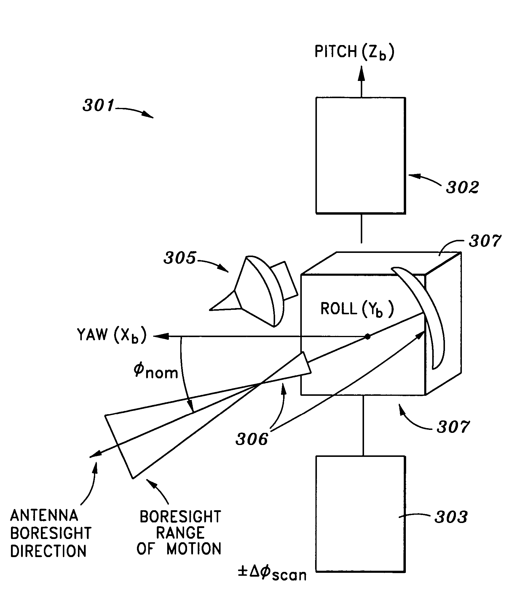
[0030] The present invention provides an LMSS for North American coverage, which overcomes the deficiencies of conventional MSS systems. Specifically, the present invention provides an enhanced LMSS using an optimized land mobile satellite configuration and steering method, which provides a favorable sun-spacecraft geometry compatible with current and future payload power and thermal requirements, without the need for yaw steering.

[0031]FIG. 3 is a diagram depicting the optimized spacecraft configuration according to one embodiment of the present invention. Briefly, the present invention is a method for configuring and operating a spacecraft in an orbit that is inclined with respect to Earth's equatorial plane, the spacecraft including at least a solar array, a receive antenna, a transmit antenna, and radiator panels. The method includes the step of nominally orienting the yaw axis of the spacecraft, the roll axis of the spacecraft, and the radiator panels substantially parallel to...


PUM


Abstract

A method for configuring and operating a spacecraft in an orbit that is inclined with respect to Earth's equatorial plane, the spacecraft including at least a solar array, a receive antenna, a transmit antenna, and radiator panels. The method includes the step of nominally orienting the yaw axis of the spacecraft, the roll axis of the spacecraft, and the radiator panels substantially parallel to Earth's equatorial plane, the pitch axis of the spacecraft and rotation axis of the solar array substantially parallel to Earth's polar axis, the Nadir vector in the yaw-pitch plane of the spacecraft, and the transmit antenna and receive antenna to angle φnom. The method also includes the step of correcting the attitude of the receive antenna and the transmit antenna to maintain a desired degree of the receive antenna and the transmit antenna steered toward a coverage region on Earth's surface.

Description

CROSS-REFERENCE TO RELATED APPLICATION [0001] This application claims priority to U.S. Provisional Patent Application No. 60 / 633,962, filed Dec. 7, 2004, which is incorporated herein by reference in its entirety for all purposes.STATEMENT AS TO RIGHTS TO INVENTIONS MADE UNDER FEDERALLY SPONSORED RESEARCH OR DEVELOPMENT [0002] Not Applicable FIELD OF THE INVENTION [0003] The present invention relates generally to optimized spacecraft configurations and, more particularly, relates to the steering of spacecraft deployed in highly inclined orbits (“HIOs”) so as to provide high performance land mobile satellite services (“LMSSs”), while maintaining a favorable sun-spacecraft geometry. BACKGROUND OF THE INVENTION [0004]FIG. 1 depicts a typical arrangement for a conventional geostationary earth orbit (“GEO”) communications spacecraft. Normally, the yaw axis of a conventional spacecraft (such as conventional spacecraft 100) is directed at Earth's center, the yaw / roll plane is parallel to th...

Claims


Application Information

Patent Timeline
IPC IPC(8): F02K1/00
CPCB64G1/1007B64G1/24G05D1/0883B64G1/244H04B7/1851
Inventor GOODZEIT, NEIL E.
Owner LOCKHEED MARTIN CORP
Why Eureka
Try Eureka