Fourier scattering methods for encoding microbeads and methods and apparatus for reading the same

a fourier scattering and microbead technology, applied in the field of fourier scattering methods for encoding microbeads, can solve the problems of high resolution, high resolution, optical techniques, and high cost of providing high resolution images, and achieve the effect of high resolution magnified images

Active Publication Date: 2006-06-08
ILLUMINA INC
View PDF99 Cites 71 Cited by
  • Summary
  • Abstract
  • Description
  • Claims
  • Application Information

AI Technical Summary

Benefits of technology

[0014] One important advantage of the present invention is that the Fourier plane analysis enables the use of a substantially less expensive code reader and code reading optics, such as a CCD array, since the code on the microbead does not have to be imaged in high order resolution in order to be interpreted.
[0015] Another advantage is that translationally invariant codes may be written over a large area when an optical filament is drawn from a preform and then cut into smalle

Problems solved by technology

However, the known ways involve using expensive, high resolution, optical techniques for imaging and reading the code off the microb

Method used


Image

  • Fourier scattering methods for encoding microbeads and methods and apparatus for reading the same
  • Fourier scattering methods for encoding microbeads and methods and apparatus for reading the same
  • Fourier scattering methods for encoding microbeads and methods and apparatus for reading the same

Examples


Embodiment Construction

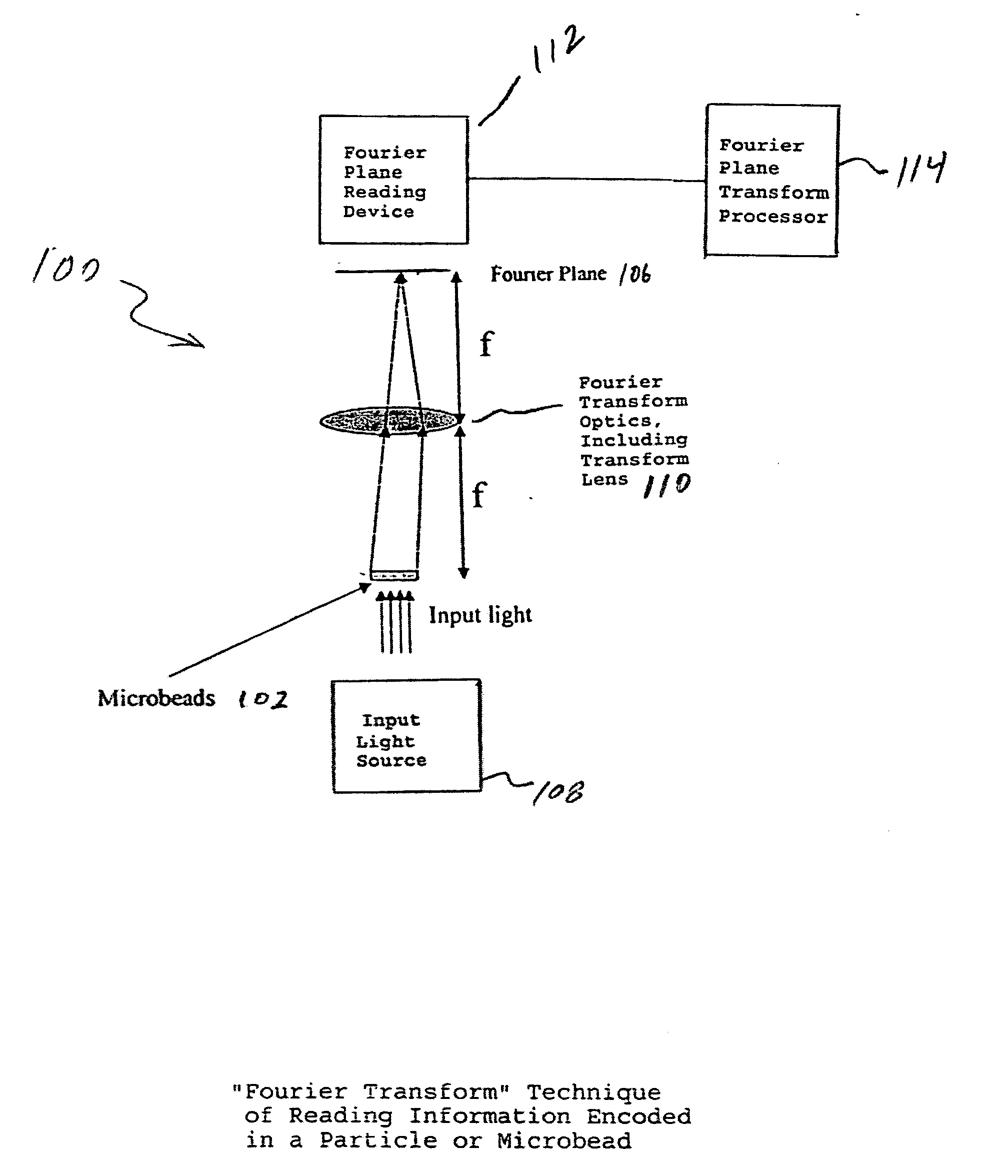
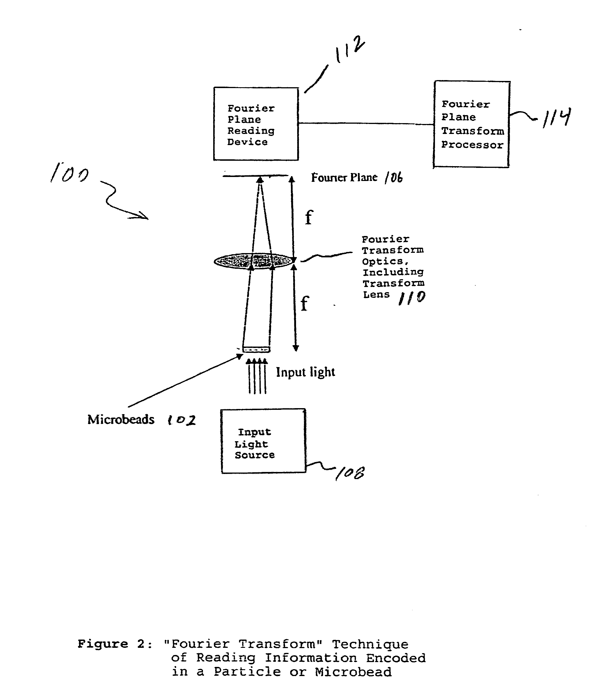
[0025]FIG. 2 shows an optical arrangement using a Fourier transform technique generally indicated as 100 for reading a microbead or other suitable optical element generally indicated 102 having a code 104 (See, for example, FIG. 3) written thereon, wherein the code 104 is projected on and read from a Fourier plane 106.

[0026] In operation, the code 104 is projected on the Fourier plane 106 by passing input light from an input light source 108 through the microbead 102 and an optical arrangement having a transform lens 110 for focusing the code 104 on the Fourier plane 106, and read on the Fourier plane 106 with a Fourier plane reading device 112, including a charge coupled device (CCD) or other suitable Fourier plane reading device and a processor for performing Fourier plane analysis. The transform lens 110 is arranged between the microbead 102 and the Fourier plane 106 at a distance of about one focal length f from each, while the charge coupled device (CCD) or other suitable Four...


PUM


Abstract

A method and apparatus for reading a microbead having a code thereon is provided wherein the code is projected on and read from a Fourier plane. The microbead may be 1-1000 microns (um) or smaller in feature size. The code is projected on the Fourier plane by scattering input light off the microbead. The scattered light from the microbead is directed through an optical arrangement having a transform lens for projecting the code on the Fourier plane, and read on the Fourier plane using a charge coupled device (CCD) or other similar device. The code may include periodic layers of material having different refractivities or phase, including index of refraction differences; periodic spatial modulations having a different phase or amplitude; a periodic binary phase change used to code information in the Fourier plane; a photonic crystal used to encode the information on the microbead, wherein a pattern of holes causes interference between incident and scattered light to form spatial and spectral patterns in the far field that are unique to the pattern of holes; or may be formed in the microbead using a single photoactive inner region, a series of longitudinal holes, different fluorescence regions, or concentric rings of material in a preform.

Description

CROSS REFERENCES TO RELATED APPLICATIONS [0001] This application is a continuation-in-part of U.S. patent application Ser. No. 10 / 645,689, filed 20 Aug. 2003, entitled “Diffraction Grating-Based Optical Identification Element” and U.S. patent application Ser. No. 10 / 661,234, filed 12 Sep. 2003, similarly entitled “Diffraction Grating-Based Optical Identification Element”; and also claims benefit to U.S. provisional patent application No. 60 / 628,897 (WFVA / CyVERA nos. 714-1.9 / CV 0056PR), filed Nov. 16, 2004, which are all hereby incorporated by reference in their entirety. [0002] The following cases contain subject matter also related to that disclosed herein and are incorporated herein by reference in their entirety, as follows: U.S. Provisional Patent Application Ser. No. 60 / 441,678, filed Jan. 22, 2003, entitled “Hybrid Random Bead / Chip Microarray” (Attorney Docket No. CC-0574); U.S. patent application Ser. No. 10 / 645,689, filed Aug. 20, 2003, entitled “Diffraction Grating-Based Op...

Claims


Application Information

Patent Timeline
IPC IPC(8): G03H1/00
CPCB01J2219/00459B01J2219/005B01J2219/00704B82Y20/00G01N15/1468G02B1/005G06E3/005G06K7/10722G06K7/10821
Inventor MOON, JOHN A.
Owner ILLUMINA INC
Why Eureka
Try Eureka